The described design can serve as an alternative laboratory the autotransformers (Latr), widely used in Amateur radio practice. In addition, this device has many advantages - no the galvanic connection of the output voltage with the network. The application of laboratory the transformer increases the safety in the food and establishing transformerless devices.
Laboratory transformer is designed for a step change of the output voltage.
The main parameters of the device
- Input voltage, V.....20
- Voltage high voltage output, .....111 269...
- The number of voltage steps.....30
- The load power, VA.....72
- Load current, A, not more than.....0,42
- Voltage low voltage output, V.....5...65
- Dimensions, mm.....240x150x140
- Weight, kg.....6,5
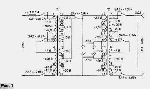
Laboratory transformer (Fig. 1) consists of transformers T1, T2, switches the output voltage SA1-SA7 and auxiliary elements. Transformers applied unified TPP-127/220-50: T1 enabled down-and T2 - raising. Accordingly, the primary winding of the transformer T1 is connected to the network, T2 to the output device. Switches SA1-SA3 and SA5-SA7 their commute primary winding, the switch SA4 - secondary the transformer T1. Output voltage values of adjacent levels differ by 2...8 %. In the initial position of the switches SA1-SA7 shown in the diagram, the output voltage equals the input.

Outlet ХS1, ХS2 form a low-voltage pad switch. The voltage at its contacts within 5...65 change In switches SA1-SA4: between contacts 2ХS1, 2ХS2 is in the range 5...10 V; outlet ХS1 - 8...15 V; between contacts 1ХS1, 2ХS2 - 13...25 V; outlet ХS2 - 20...40 V; and between the contacts 1ХS1, 1ХS2 - 33...65 V. the low voltage load Current output is not more than 1.1 A. Number steps voltage is equal to 80. Laboratory transformer ensures accuracy the installation of small voltage at the low voltage output higher comparison with autotransformer Latr.
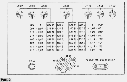
The device is assembled in a metal case. At the base and the walls of the housing made holes for ventilation. Indicate on the front panel (Fig. 2) explain the management of a laboratory transformer and contain some of his options. Above each switch specified dial-up coefficient them transformation. For example, if only the switch SA3 (indicated by "(0,95"), this means that the transformation ratio of the device equal to 0.95; accordingly, the output voltage - V. 209

The long axis of symmetry rosettes RD-1 low voltage switch and parallel are located at an angle of 60 o to the horizontal. The distance between the centers of the mounting holes of sockets 19 mm., the Centers of the upper left contact of the socket (1XS1), the upper right contact of the socket (1XS2) and its lower contact (2XS2) form the vertices of an imaginary equilateral triangle with the side 19 mm - the distance between the contacts of a standard plug. Low-voltage pad switch provides five different kinds of connection plugs.
Depending on the required power laboratory transformer and settings low-voltage output can be applied unified transformers CCI with a capacity of 1.65...207∙A, having the designation"127/" [1, 2]. For homemade transformers use magnetic Sh. Switches SA1-SA7 - microtubles MT-1 or similar. Dual microtubles MT-2 in parallel the inclusion of two sections cannot be applied. The asynchronous operation of sections will lead to the circuit switched part of the winding at the time of switching, so permissible current of one section of microtuber (3) shall not be less than the current intermediate windings. The device can also be used transformers TA, TN, TAN, having the designation "127/" [1]. Switching windings only network transformers CCI and TN 29 provides the output voltage steps, TA - 17, TAN - 5. All transformers CCI switchable windings connected in successive intermediate circuit. About 10% of the transformers TA and 15 % transformers TN have groups of secondary windings, calculated on the same current value, and also allow them switching.
Literature
Author: A. Trifonov, St. Petersburg


