


")

The proposed compact the power supply unit (PSU) is installed in the integrated circuit L4960 company SGS-Thomson Microelectronics, representing an adjustable switching regulator DC voltage, which provides output current up to 2.5 A at an output voltage of 5…40 V IC has built-in protection against over temperature, over current and short circuit in the load circuit. This unit is designed to power various electronic devices that consume power up to 25 watts.
Schematic diagram of the device represented in Fig. 1. Mains voltage 220 through the fusible fuse FU1, contacts switch SA1 and noise filter comes C4L1L2C5 to the primary winding of the step-down transformer T1, the Switch SA1 is built-in indicator - discharge lamp. The resistor R1 extends the lamp life of the switch and reduces it to heat up.
The voltage of the secondary winding of the transformer via resettable fuse FU2 comes on the bridge rectifier diodes Schottky VD4-VD7. Application such diodes reduces the power loss in the rectifier and, accordingly, the heating its elements, as well as approximately 1 In rectified voltage increases on the capacitor filter C3. Resetable fuse FU2 protects the transformer from overload fault rectifier circuits DA1, and if the "errors" this protection systems.
System overload some integral switching regulator, for example, LM2575T, LM2576T may fail if as a load is connected powerful constant current generator or other switching regulator of comparable capacity. Varistor RU1 protects network the transformer and the rectifier diodes from surges and surge network voltage. Output voltage adjust variable resistor R5 in the interval from 5 to 18 V. Upper circuit position of the slider of the variable resistor corresponds to the minimum output voltage.
Operating frequency of the chip DA1 about 95 kHz. The shape of the voltage at circuit output (pin 7) rectangular, the duty cycle depends on the output, input voltage and load current. Resistor R6 and diode VD1 protect the chip from damage, for example, when making a sharp turn engine AC resistor R5 or connected to the output of the PSU charged capacitor of a large capacitance. In case of overload the output of the regulator is built in to the chip protection disables the output voltage and after about 0.5 s is trying to start again.
The inductor L3 is cumulative. Two-tier filter C9-C12L4C17-C19L5C20-C22 reduces the ripple of the output stabilized voltage. The oxide capacitor S9 for high-current high-frequency fluctuations have increased the risk of degradation, so he shunted ceramic capacitors C10-C12 Similar solution applies to the oxide capacitor C3.
Relay K1 includes the power led when HL3 the load current is more than 1 A. This allows you to quickly track increased power consumption, for example, USC in silent mode. The current release of the relay contacts is about 0.6 A. the relay Coil K1 also included with the filter.
On the microammeter RA1, the Zener diode VD8 and resistors R10, R11 performed voltmeter, which measures the output voltage of the power supply. The Zener diode VD8 and resistor R11 provides a "stretch" of the instrument scale PA1.
When the closed contacts of the switch SA2 protection of the load and the stabilizer thanks to integrated sites circuits DA1, and in the event of its failure - a self-restoring fuse FU2. Resetable fuse FU3 on current of 0.75 And is designed to protect sites of low-power loads. The switch allows SA3 to quickly disconnect the load from the power supply and thereby reduce the chance of damage powered equipment.
LEDs HL1, HL2 highlight the scale of the instrument RA1. The led indicates HL4 the presence of voltage at the output of the stabilizer DA1, a HL5 - presence the voltage across the load.
The PSU is mounted in the metal casing dimensions 178x160x49 mm imported from the old receiver. The body is pre-painted black automotive lacquer BT-577 and subjected to drying, first for 12 h at room temperature, then twice for 40 min at 180°C and another 12 h at room temperature. This mode prevents the appearance of bubbles on the surface. Drying painted casing only at room temperature may take six months. Before painting in the bottom and side walls of the body drill 100 200…vent holes of diameter 3 mm.
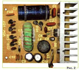
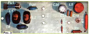
The majority of construction components placed on two boards, Fig. 2 and Fig. 3. The installation is made in hinged way. High-current connections are copper installation wire with a diameter of not less than 1 mm. pin 4 of the IC, diodes VD2, VD3, capacitor C9 should be connected to GND individual conductors. To connect a metal enclosure and a common wire need at the point. defined in the diagram the ground symbol (see Fig. 1). Correct wiring power and signal circuits are critical to the excellent work of PD.
The transformer T1 - TA-30-2 from a portable black and white TV "Youth". With this transformer with mains voltage 220 V unit supply provides the output voltage of 12 V At a load current of 2…5 A. When a larger voltage maximum output current linearly decreases to 0.5 A at the output voltage of 18 V. to increase the output current up to 2.5 a at a voltage of 18, you should use a transformer with an overall capacity of not less than 60 W and the open-circuit voltage in the secondary winding 22…27 V. But this transformer may not fit in the housing of the specified sizes
Chip installed L4960 on ribbed dural sink with a total area of 100 cm2 cooling (one side), isolated from the housing.
The inductor L3 is wound on the annular magnetic core Chg ferrite NM. Winding comprises 30 turns homemade Litz wire composed of 33 pigtails sew-2 0,13. Before winding in the magnetic circuit must be done non-magnetic gap, for then the ring is broken in the grip of two parts and glued instant superglue. Then the ring successively dried for 2 h at room temperature and 6 h at 60°C. Then the ring obmanyvajut and varnished cloth two layers of coil winding. Between the layers need to lay one layer of varnished cloth. If the power unit is designed for high output power (18 V, 2.5 A), you must use either two glued together such rings or the magnetic core is larger. Non-magnetic gap is required. The throttle is mounted in a rectangular hole in the circuit Board and fixed silicone sealant. Permissible use of any similar throttle inductance to 150.3…50 µh. Other chokes industrial manufacturing. L1, L2 - LCHK-007, L4, L5 - BNC-007 on the N-shaped ferrite magnetic circuits with a current capacity of at least 3 And, with the resistance of the windings 30 mW.
The role K1 homemade, 23 revolution of PEV-2 0,51 wound on the cylinder of the reed switch. CAM-2 Switch SA1 - IRS-101-1 A3 or IRS - 101-12C with built-in lamp of the glow discharge. The switch SA3 - button the current no less than 3 And, for example, KDC-AT, SDDF-3 Similar domestic switches. PCN-1-2 have significantly shorter life spans and stiffer recoil spring.
LEDs HL1, HL2 - RL50-WH744D white color luminescence (8000 MCD), they can replace any with high luminous efficiency. In front of their lenses set translucent matte light diffusing film. LEDs HL3 - RL30-RD314S red, HU - RL30-YG414S green, HL5 -RL30-yellow HY214S emission colors can be substituted with, for example, from CIPD.
Diodes can SR306 replace SR360, MBR360, 31DQ06 Instead UF4004 diodes will fit any of the 1N400x series, UF400x, CD, CD, CD. Zener BZV55C-replace 3V6 on 1N4729A, TZMC3V6, G2S3.6.
Variable resistor R5 and import of compact linear characteristic the relationship between resistance fragile rotation. The variable resistor body connected to the common (negative) wire, but must be isolated from the hull design. The signal wire coming from the variable resistor, R6 should to be screened. The remaining resistors - any type of General application appropriate power. Varistor RU1 - MYG10-471 can to replace a similar disk FNR-10K471. FNR-14K471 TNR10G471. Capacitors C1, C2 - ceramic for a rated voltage of not lower than 50 V. the Capacitors C10-C12, C17, C21, C22 - ceramic for a rated voltage of not less than 25 V. the Capacitors C13-C16 - ceramic or film for a rated voltage of not lower than 50 V. the Capacitors C6, C7 - film. Oxide capacitors - import analogues C50-68. Capacitors C4, C5 - imported ceramic for a rated voltage not below 400 VAC / 630 VDC. From the quality of these capacitors depends largely on the security of the operation of the PSU. You can apply the capacitors K15-5 on the operating voltage below 1600 In
Microammeter RA1 - M68501, from domestic tape recorder. Variant of the instrument scale size 40x20 mm it is shown in Fig. 4.
The scale is drawn in simple to master Nero Cover Designer - graphic vector editor from the software package Ahead Nero version 8. The graduations of the scale produced in the working position of the device.
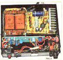
View of the layout of the nodes in the case of PD is shown in Fig. 5.
Unmistakably made of serviceable parts in the power supply starts to work immediately and almost does not require networking. If necessary, the selection of the resistor R2 install the upper limit of the output voltage and the selection of the resistor R10 is required the sensitivity of the voltmeter.
A small level of electromagnetic radiation PSU and pulsations voltage at its output allowed the author to put this PSU powered from him same homemade pocket double circuit. УSW radio, assembled in the first half of the 90s on the chip CHA. The radio reception is carried out in concrete the house on the built-in telescopic antenna without any noise and squeaks with a distance of 30 km from the tower.
Author: A. Butov, S. CORBA Yaroslavl region