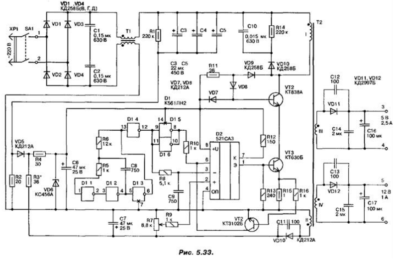
Electrical diagram of a single-pulse Converter is shown in Fig. 5.33. It operates at a frequency of about 50 kHz.

At the time of power-up the capacitors C3...C5 is charged through the resistor R2. At that time a voltage pulse from resistor across the diode VD5 and resistor R4 acts on the capacitor C6 and charges it. The Zener diode VD6 limits the voltage level of power the chip to a value of 5.6 V. This provides initial launch circuits and the power supply to the oscillator. In the future, the necessary supply voltage for the circuit is removed from the secondary winding (II) of transformer T2.
On the elements of the chip D1.1...D1.3 assembled master oscillator pulses from which on the capacitor C9 is formed sawtooth voltage. The Comparator D2 will compare the voltage of the saw with the voltage level at the input 2 In the source the state of the comparator is open and through the resistor R12 and the base of transistor VT3 current flows. In this case, VT3, and hence VT2, will be open. Once voltage winding II of transformer T2 exceeds resistor R7 the threshold, the comparator will close, which will limit the pulse duration in primary winding of the transformer. Thus, stabilization of the output voltage when the network input.
The stabilization factor Converter depends on the slope of the saw on the capacitor C6. Transistor VT1 protects the power supply from overcurrent. When opening actuates the locking operation of the comparator (when a logical "0" on the pin 6 of the chip D2). The latch signal is periodically is also fed from the output of of the generator. This eliminates the finding of the comparator in the open state for a long period of time. In case of tripping, to return to the circuit in working condition (to run), you will need some time to turn off the power supply from the mains (the capacitors C3...C5 is discharged through the resistor R1).
In the scheme used parts: resistors R1 - MLT, R2 is C5-5 1 W, trimmer R7 - type. SP5-BWA-0.25 W, capacitors C1, C2 I. C10 - type CU-2, C3,..., C5 - C50-29 450 In, C6, C7 type K50-35, C8, C9, C11, C15 - K10-17.
The transistor VT2 can be replaced by CTA. The filter choke T1 is performed on two United together ferrite ring cores MNM size CHH,5. Both windings contain 40 turns of wire PEL-2 with a diameter of 0.33 mm (before winding the sharp edges of the core must be rounded with a file). For the manufacture of transformer T2 is taken ferrite (MNM) Cup size. <url>. In the Central part of the magnetic circuit must have a clearance of about 0.2.0.6 mm (the transformer is not magnetized at work). Coils contain: 1 - 120 coils; II - 7 turns of wire PEL-2 with a diameter of 0.15 mm; III - 8 turns of wire diameter 3x0,33 mm (three wires wound simultaneously), IV - 19 turns with a diameter of 0.5 mm.
The transistor VT2 is installed on the radiator, and the whole structure is closed a mesh screen (for heat removal from T2 and VT2). The screen allows you to reduce the level radiation and interference source. Before switching transformer T2 you must verify that the pulse-forming network output D2 (pin 1). To do this, you can temporarily apply power 9 V on capacitor C7 from external source.
With proper phasing connect the windings of transformer T2 schema settings is to install a resistor R7 desired value of tension the secondary winding and verification of launch of the scheme at minimum supply voltage 180 V.
Author: A. P. Seman


