


")

Bypassing outdated standard PWM modulators, let's start with the more advanced schemes BP, using the work of switch power switch at zero current of the inductor, or foreign - off-line switch. These schemes differ from conventional very high efficiency, low noise level, and the choice of the appropriate element base - simplicity of design and ease of configuration.
Figure 1 shows the diagram of the power supply power 70W to power stereo amplifier within hit. Power Converter built on a chip KA2S0880, which includes all the necessary components for the construction of a primary part of the block power. It should be noted that the Fairchild Corporation by developing this chip, have tried to cool the chip is very stable in operation and has all the necessary protections. Assembled on the basis of this chip the PSU has realindustry.ru protection against overload and short circuit protection load at an emergency exit stresses beyond valid, the possibility of introducing a sleep mode. An obvious disadvantage of this scheme - the unit does not operate at full load. First you need to enable it separately, then loading.
Features:
Power supply voltage: 200…240 V Output voltage: Without load. . . . . . . . . . . . . . . . . ±16,5 In At full load. . . . . . . . . . . . . . ±15…±15,5 In Output power maximum long-term she's limited by the chip. . . . . . . 70W Operating frequency. . . . . . . . . . . . . . . . . 20kHz The efficiency of the device. . . . . . . . . . . . . . . . . 90…93%
(click to enlarge)
The PSU is designed for symmetric the load at which the consumed current by the plus and minus equal - amplifiers woofers. Unbalanced load causes overvoltage on one of the shoulders and the unit may go into protection. In the selection of parts will not forget the requirements to the parameters and design of the device. Rectifier diodes must be with a reverse voltage of at least 200 Volts, the capacitors C11 and C12 deliberately selected for a voltage of 50 Volts, i.e. large - case that they will be heated, at frequencies of about 20-30 kHz them the minimum impedance, which is effective suppression surges, and, as a consequence of heating. Pay attention to the appearance of the components, especially the chips and rectifier diodes - scratched, dull, ugly body says anything about poor quality making the items, either on the "left" production. Do not use the capacitors K73-17, they often fail. The chip can to make any firm Fairchild, either Samsung (SEC)
Schemes that have transformers, very critical to the phasing of windings. When the phasing of the windings is required to make so that the beginnings and ends of the windings connected to your points in the circuit. If the phasing is incorrect, the winding will operate in antiphase, thereby breaking the circuit and may damage the components. Start winding on the diagram marked with a dot at one of the output windings. It's like the speakers - conclusions marked advantages. Your best to wind the windings on figure 2 - as option 1 or option 2, but not mixing these options .
So we will be better placed to understand what is the conclusion going to be the beginning, and for what end. An example of the phasing of the windings is in figure 3, dots show the start winding.
The transformer is wound on a core of SH ferrite M2000, with a gap in the magnetic circuit of 0.2 mm. Primary winding Widow divided into two equal parts. One part is wound in the first layer, the second in the latter. Between them there are secondary winding: output - 7+Vitkov two wires in each coil power circuits - 7 of turns. All windings are wound with a wire diameter of 0.6 mm Gap do with using paper, glued it to the ends of the ferrite, putting everything together with coil and magnetic circuit sizing with superglue.
Block assembled with no errors in the installation begins to work immediately and without glitches. However, to protect yourself from possible errors, will hold the first turn on the device step by step.
Instead of the fuse enable basic lamp 220V 100W. It will prevent possible damage to the chip. Will olpaem Zener the thyristors. To the output of the power supply between "+" and "-" connect the load - nichrome spiral 30-40 Ohms power not less than 100 watts. We will only be used to check the power supply. These spirals are sold in shops for the repair of heaters or slink separately or in a glass tube. We need only a part of the spiral. Need resistance measure out the tester and connect to the output of the power supply. Not forget that the spiral is connected between the "+" and "-" source, and the voltage measurements we will lead from the common wire (GND). Connect the tester to the "+" output from the power supply and turn the unit into a power outlet. A second the output should be set voltage +16.5 volts. Wait 5 seconds, turn off block and look of heating parts. If there is suspicious is hot elements - do not leave unattended!!! Don't forget that just gathered AC adapter, which has a "hidden", but powerful destructive power: a) If the output voltage is greater than Walt, for example, 20, Walt means, the feedback circuit. This may either because of errors in the scheme, either because of faulty parts. Need will have to check. If the voltage is less Walt and for 5 seconds much hot chip, then we incorrectly phased secondary winding relative to the primary.
It may happen that the unit is switched on in the network output nothing :( In this case, check the voltage on the network the capacitor is about Wat, the voltage on the third leg of the chip with respect to the primary common wire (pin 2). It should jump in 12-Walt is a microchip tries to run, but something in her prevents. Will check the chain feed of the auxiliary winding and rectifier, phasing of the windings. If everything is correct - perhaps the chip went into protection because of a short circuit in the load, fault rectifier diodes, overload. Turn off the unit and wait for the discharge network capacitor below Walt and try to turn on again with connected not spiral 30-40 Ohms, and 50-60. It is also possible that the diodes D 4 and D 5 are not able to work at high frequencies, that is not suitable for this scheme. In this case, the transformer whistle, straining, poor :( If it didn't work out, let's remember how many turns we reeled and how :). If the voltage at the third output of the chip goes far beyond the limits Walt, for example, 30, Walt, we have too many wound of turns on the secondary winding or the winding is again incorrectly phased with respect to the primary winding.
The next step is to test the unit without load. Is to check the feedback circuit to stabilize. She is the optocoupler. The desired output voltage is set Zener diode D 6, it will be above half a volt than Zener diode: a) If the spiral we measure exactly the required voltage, ie 15-Walt, then disconnect the load. The voltage should not change, well volt and a half, we do not interfere. Will immediately disconnect the unit from the outlet when no load voltage will increase dramatically, otherwise you can kill rectifier diodes, capacitors and the optocoupler.
Next - check the protection of the load in excess of the the output voltage. The protection is triggered in emergency mode, without attempting to restart the unit. Protection exists on the plus shoulder and sub-zero, and they work independently, and the effect overall :) the work is arranged a short circuit at the output, which the chip goes into protection. Thyristors have a good performance, and in the accident just a couple of milliseconds since the load power is removed. If suddenly, in the future, this circuit will work, then you need to check the power supply with the beginning by the same technique. To check forcibly raise the output voltage of a few volts. To do this consistently with Zener diode enable one to several volts is 4.7 or 5.1 or 6.2 V. Short-circuit his jumper and switch on the unit. Measure the output voltage in normal. Break the jumper, the transformer must "technote", and the block to disconnect. Waiting for discharge capacitor network, put the jumper and included. Output voltage should be set to normal.
If all the unit tests worked without glitches, we hang up his load 15om and leave for half an hour. Then the device is found fit for service to the Fatherland. :)
Mounting the PCB
The printed circuit Board is developed separately under the specific design of the frame of the transformer and its Pinout.
When designing the PCB must be considered the following points:
Associated with each other the details are not spread far from each other. On the tracks flow pulse currents, interference emission into the surrounding space, and the longer the path, the greater the noise. Between tracks maintain the network portion a sufficient distance. If between a number of walking tracks the voltage of 200-300 volts, the distance between them should be not less than 4-5mm. Also observe the distance between tracks and parts of the network and the secondary part. The only the component that we have nothing to do optocoupler. She's the distance between the legs about an inch, all other distances between network and secondary part should be at least 1cm. On the secondary side track from the optocoupler must connect as close to the diode D 4. To track withstand high currents, it is often filled with solder. But you can do it not with each track. If possible, let it will be wider than the thicker, otherwise between thick paths will be a parasitic relationship, which may produce noise at the output, and to do many more dirty tricks. Capacitors C15, 16 C must be connected closer to the diodes, and not to electrolytes C11, C 12. IT IS VERY IMPORTANT!!!! Watch figure 4.
The track comes from diode D1 to ceramic the capacitor C1, from him to the electrolyte C2, from it to the coil L1 - so it is correct.
Figure 5 - so wrong.
Track, on which hangs a few elements, should BYPASS every one of them, and not to go past. In a pulse technique is often very important millimeters the distances. For example: figure 6.
If the mount point ceramic the capacitor C1 to be 5mm further away from the diode D1, stabilization worse on polpolita, the efficiency will drop by 1%.
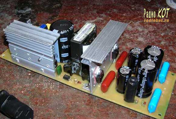
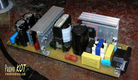
But photos of the assembled prototype:
Publication: www.radiokot.ru, www.cxem.net