


")

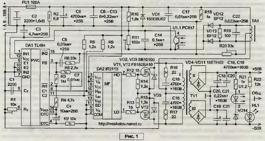
The article considered the switching power supply has a high efficiency and high output power with a smaller number of used and cheap common electronic components. Dollary the output of the device has galvanic isolation from the mains. Schematic diagram of the source supply is shown in the figure below:
(click to enlarge)
Main technical characteristics
- The AC voltage supply network, ............ 220 +10% -20%
- Constant output voltage, ..................... 75 + 75
- The maximum output power, W................... 750
- The self-refresh frequency, kHz................................... 8
- The maximum efficiency of the device, % .......................... 92
The prototype device is the device described in the article [1]. Fees complete ease are the lack of stabilization of the output voltage and protection against overcurrent and also rather low frequency conversion, lying in perceivable by the human ear frequency range. Due to the above disadvantages our power source is recommended for use in specific applications outside the premises, such as in the garage.
The power pulse the power source is able to give to the load, is approximately equal to one horse force. In Belarus, the Russian Federation and other countries of Europe, the horsepower call this power, which allows for 1 second to lift the body weighing 75 kg or 1 meter. This horsepower, called metric, is strictly 735,49875 watts. In the United States believe that horsepower corresponds to the power in 745,6999 watts. And under electric horse power mean power in 746 W. Due to the ambiguous definition of horsepower this term is not often use.
The appointment and replacement of components
The power switch SA1 is possible to apply a keyboard type brand UV (250 V, 8 A) VA (250 V, 16 A) or V, SWR74 (250 V, 16 A). In the author's version was used power switch. The thermistor RK1 reduces the amplitude of the pulse current consumed by capacitors C5, C6, C9 and SUE during their charge when turn on the power source to the network. Mark NTC-thermistor - B57364-S 100-M (7,5 And, 10 Ohms). Fuse FU1 feeding protects the network from overload in the event failure of components of the apparatus. Mark fuse - WPB-1, ITSB-1B, VPST-S, or VPB-40. Varistor RU1 protects the input components of the power source from overvoltage. Mark varistor - CNR10D431, CNR14D431, CNR20D431, CNR10D471, CNR14D471, CNR20D471, TVR10431, TVR14431, TVR20431, TVR10471, TVR14471, TVR20471 or S14K275. The capacitor C2 and Duhovoj-tion inductor L1 form a l-shaped network filter prevents high frequency noise from pulse Converter to the mains supply.
Dual choke L1 has been selected brand B82725-A2602-N1 manufactured by "Epcos". This choke has inductance 2x3,9 mH and designed to operate at a voltage of 250 V for alternating current power to 6 A. as a substitute, you can apply the same the throttle brand B82725-A2103-N1 the same manufacturer with inductance 2x1,8 mH and allowing the flow of current intensity up to 10 A at AC voltage of 250 V. the two-Winding inductor L1 can be made independently. For this two-folded along a semicircular magnetic from MO-permalloy MP or MP size Khh,5 stack winding wire brand pelsho diameter of 0.98 mm to populate the window of the core. Before laying the windings, the magnetic core is covered with a layer of insulation, for example, of varnished cloth or Teflon. So arrive and in the manufacture of pulse transformers TV1 and TV2. It is important to ensure that the wrapping wire is not selling and not cut through the insulation layer. The windings are placed simultaneously in the two wires.
Capacitor C2 is designed for operation at alternating voltage up to 300 V, you can take brands V-A-M or V-S-M manufacturing firms "Epcos". Fixed resistors R2, R3 and bipolar transistors VT1, VT2 form the analogue of diacs. Instead of analog dynistor you can use a dinistor brand CNA or DB3 of ST Microelectronics". The capacitor C1 at the time of the charge when the device consumes the current flowing through the winding I of the matching transformer TV1, creates an initial control signal transistors key. Capacitor C1, and also the capacitors C3…C6, you can take the brand K73-17. Amperage charge capacitor C1 limits the DC resistor R1.
Diode Assembly VD1 and capacitors C5, C6, C9 and XU represent the network rectifier with capacitive filter, which forms a voltage divider. Fixed resistors R11 and R12 remove the charges from the capacitors C5, C9 and C6, XU respectively. Electrolytic capacitors C7 C10…you can use the brand C50-35 or similar. Diode Assembly VD1 is permissible to change the instruments SR, SWРС1008, LWU10К, BR1010, PBU1007, LWU10M, LWU1010, RS1007nnn SWРС1510.
Matching transformer TV1 performed on a single toroidal magnetic core size CHH ferrite MNM-17. All three windings, which are placed the magnetic core at the same time, contain 8 turns of wire pelsho diameter of 0.5 mm.
Fixed resistors R4 and R5 limit the currents bases of bipolar transistors VT3, And VT4 VT5, VT6, respectively.
Powerful bipolar transistors VT3.. .VT6 serve as switching components the Converter. Transistors brand TA can be exchanged for CTA, CTA or, what's worse, CTA. Transistors VT3 VT6…you should install four independent cooler with a useful area of each of about 140 cm2. Permanent resistors R6 R9…equalize the currents of the emitter bipolar transistors VT3 VT6…and are the elements of the circuits of the local feedbacks that accelerate switch the transistors. Without these resistors transistors key fails because overload the stream. Resistors R6 R9…should have the least possible parasitic inductance, as otherwise the key transistors will be put out of action.
Each of the equalizing resistors valid to be included ten of fixed resistors in parallel MLT a resistance of 1 Ohm and power of 0.25 watts. Diodes VD2…VD5 brand HER508 -damping. You can exchange them for diodes 8ETX06S, BYC10-600, HFA04TB60, HFA08TB60 or similar. Limiting the current of the constant resistor R10, winding I transformer TV1 and winding I of the transformer TV2 form a chain of positive feedback, thanks to which the Converter supports auto generation. Resistor R10 can be composed of five resistors with a capacity of 2 watts, which are connected in parallel.
Pulse transformer TV2 performed on four stacked along the annular magnetic cores size CHH ferrite MNM-A or MNM-17. Winding I consists of 10 turns of wire with a diameter of 0.5 mm, winding II -103 turns with a diameter of 1.00 mm, and the winding III - 51 + 51 coil diameter of 1.6 mm is Permissible to use magnet wire with enamel insulation brands PAT-200-1, PAT-200-2, PETD-180, PETV-1, PETV-2, PEA-130-MACK, PEE-130-MACK, PAEI-200, PAAI-200 or PEF-155. Winding and insulation cover exercise tapes from the varnished cloth. Diode VD6…VD9 straighten pulse the tension on the winding III of the transformer TV2, and smoothing capacitors C3, C4, C7 and C8 filtered from the variable component. These the diodes can be taken brands AT, 15ETX06S or part no dsei12-06A. The diodes should mounted on four separate cooler with full surface area each approximately 50 cm2.
Setting
Before switching on the appliance to the network, remember that some of the components is under dangerous voltages. Observe the safety rules.
Typically, the power source, if collected from the healthy parts and accurately according to the scheme in setup is not required and begins to work immediately, without establishing. However, if auto generation't have any, you should try to change the phasing of inclusion winding I of the transformer TV2. Frequency conversion can try to increase about 25 kHz, if used as a magnetic core matching transformer TV1 toroidal core of smaller diameter, is made of ferrite with high magnetic permeability (at least 2000…3000). From this, it unfortunately, will increase the losses in the core transistors VT3 VT6…, and the efficiency of the source power will be less. This happens due to the fact that the pulses in the windings II and III matching transformer TV1 will have a more flat fronts.
Literature
Author: E. Moscato, Taganrog, http://moskatov.narod.ru