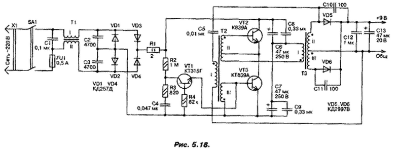
Converter (Fig. 5.18) is designed to supply 220 V devices quiescent current up to 3 A at an output voltage of 9.2 In (to get out of this 5 V or 6 can be used In any linear model scheme stabilizer). The proposed Converter differs from a similar simplicity and the availability of protection power supply from overload in the output circuit in the case short-circuit. The electrical circuit consists of an input filter (elements C1, C2, C3 and T1); chain running (R2, R3, R4, C4, VT1); oscillator (VT2, VT3, T2, T3,...C5 C9); rectifier low voltage (VD5, VD6, C10 C13...).

The transducer is assembled in a common half-bridge circuit. Input filter Converter provides attenuation of noise from the frequency 15 kHz more than 2 times. In the circuit of the starting transistor VT1 is used in reversible mode breakdown that allows you to create short pulses, which are necessary at the moment turn on the circuit to start the operation key stage VT2, VT3 mode of the oscillator at a frequency of 30 to 60 kHz, the operating frequency, small the limits can be changed capacitance C5. In the case of the circuit of the secondary winding of the transformer T3 feedback in the oscillator is disturbed and generation breaks down until the fault Converter efficiency at a current 2 load And is 0.74 (at load current of 4 A is reduced to 0,63).
The device can be used any type resistors, capacitors C1 type K73-17 630 V; C2, C3 type K73-9 or K73-17 250 V; C4, C5 type K10-7; C6, C7 type K50-35 250 V, C8, C9 type K73-9 250 V; 10.C12 type K10-17; C13 type K52-1B at 20 V. the Transistor VT1 can be replaced by CTA, B, C, transistors VT2 and VT3 on KT838A, CTV. The throttle T1 is wound on two glued together ring cores size CHH ferrite brand 2000NM. The windings I and II each contain 45 turns of wire sew-2 with a diameter of 0.25 mm.
The transformer T2 is made of two glued together ring cores size KHz ferrite 2000NM. Winding I contains 60 turns, winding II and III - 15 turns of wire PELSHO-0.15 (dissipation in the winding II for feedback current from the third round).
For manufacturing. T3 is applied to the annular core Chg (2000NM). Winding I wrap 250 turns of wire sew-2-0,25, winding II and III - 22 turns wire sew-2 with a diameter of 0.51 mm. In the manufacture of transformers before the winding of the wire must be rounded with a needle file the sharp edges of the core and wrap them varnished cloth. The winding should be round, followed insulation of each layer (it is better to use Teflon tape with a thickness of 0.1 mm).
Used diodes VD1.VD4 can be replaced with any high-voltage, replacement diodes VD5 and VD6, except on CDW, another type is not recommended. Most of the dissipation occurs in the circuit for the rectifier diodes VD5, VD6, and they must be installed on the radiator.
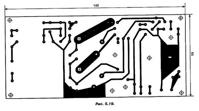
Other details of the scheme in the heat sink is not needed. Structurally, all the elements the scheme, in addition to the switch S1 and diode VD5, VD6, placed on unilateral printed circuit Board size 140x65 mm. a printed circuit Board shown in Fig. 5.19.

Prior to the initial inclusion of the Converter must check phase windings in chains VT2 and VT3 base schema. If the inverter when proper installation is not immediately starts to work, you will need to swap the winding I of the transformer T2 In conclusion, it should be noted that, using this circuit, you can also obtain other voltage in the secondary circuit, what needs to change in proportion to the number of turns in the secondary windings II and III of the transformer T3.
Author: A. P. Seman


