Switching power supplies are widely used in modern electronic equipment. Increasingly began to use them and hams, what reflected in the increased number of publications in the electronic literature, particularly in the magazine "Radio". However, in most cases describes a relatively low-power design. The author of published article readers pulsed power supply 800 watts. From the previously described he is in the inverter field-effect transistors and transformer with the primary winding with the secondary output. The first provides higher efficiency and reduced levels of high-frequency interference, and the second half less current through transistors key and eliminates the need for decoupling the transformer in the chains of their locks.
The drawback of this scheme solutions - high voltage on the primary halves winding, which requires the use of transistors with a corresponding valid voltage. However, unlike bridge Converter, in this case only two transistors instead of four, which simplifies the design and increases The efficiency of the device.
In the pulsed power supplies (UPS) use one - and two-stroke high-frequency the converters. Efficiency first is lower than the second, so a single power UPS more than 40...60 W to design impractical. Push-pull converters can provide a much greater power output with high efficiency. They divided into several groups, characterized by the method of excitation output of the switching transistors and switching circuit in the circuit of the primary winding the transformer of the Converter. If we talk about the mode of excitation, it is possible be divided into two groups: a self and external excitation. First are less popular because of the difficulties in establishing. When designing powerful (over 200 watts) UPS the complexity of their manufacturing unreasonably increases, therefore, for such power sources are of little use. Converters with external excitation is well suited for the creation of the UPS increased power and sometimes almost not require building.
As to the connection of the switching transistors to the transformer, here there are three schemes: the so-called half-bridge (Fig. 1, a), pavement (Fig. 1, b) and with the primary winding having a tap from the middle (Fig. 1, in). Today day the most widely half-bridge Converter [1]. For it requires two transistors with a relatively low voltage value IKE max. As can be seen from Fig. 1, and. capacitors C1 and C2 form a divider voltage connected to the primary (I) winding of the transformer T2. When the opening of the key transistor pulse amplitude of voltage on the winding reaches the value u n and m/2 - IKE max.

Bridge Converter [2] a similar half-bridge, but it condensers replaced by transistors VT3 and VT4 (Fig. 1. b) that appear in pairs the diagonal. This Converter has a slightly higher efficiency due to the increasing the voltage applied to the primary winding of the transformer, and hence, reduction of the current flowing through the transistors VT1 - VT4. The amplitude of the voltage across the primary winding of the transformer in this case reaches the values of u pit - 2Uкэ max.
Apart is the Converter according to the scheme in Fig. 1. V. consumed the most The efficiency. This is achieved by reducing the current in primary winding I. as a consequence, reducing power dissipation in transistors key, which is extremely important for powerful UPS. The amplitude of the voltage pulses in the half of the primary winding rises u pit - IKE max. It should also be noted that unlike other converters (1,2) it is not necessary for the input decoupling a transformer.
In the device according to the scheme in Fig. 1. in it is necessary to use transistors with high value IKE max. Since the upper end (the scheme), half of the primary winding connected to the lower early, when the current flows in the first (open VT1) in second, it creates a voltage equal in magnitude to the amplitude of the voltage at the first, but opposite in sign relative to u pit. In other words, the voltage at the private collector of transistor VT2 reaches 2Uпит. so it IKE max should to be more 2Uпит. The proposed UPS applied push-pull Converter with transformer, the primary winding of which has an average output. He has a high efficiency. low ripple and poorly radiates noise into the surrounding space. The author uses it to power two-channel omednennaja option of USC. described in [3]. The UPS input voltage - 180...240 V. rated output voltage (at the input 220 V) - h V. maximum load capacity - 800 watts. the transducer operating frequency is 90 kHz.
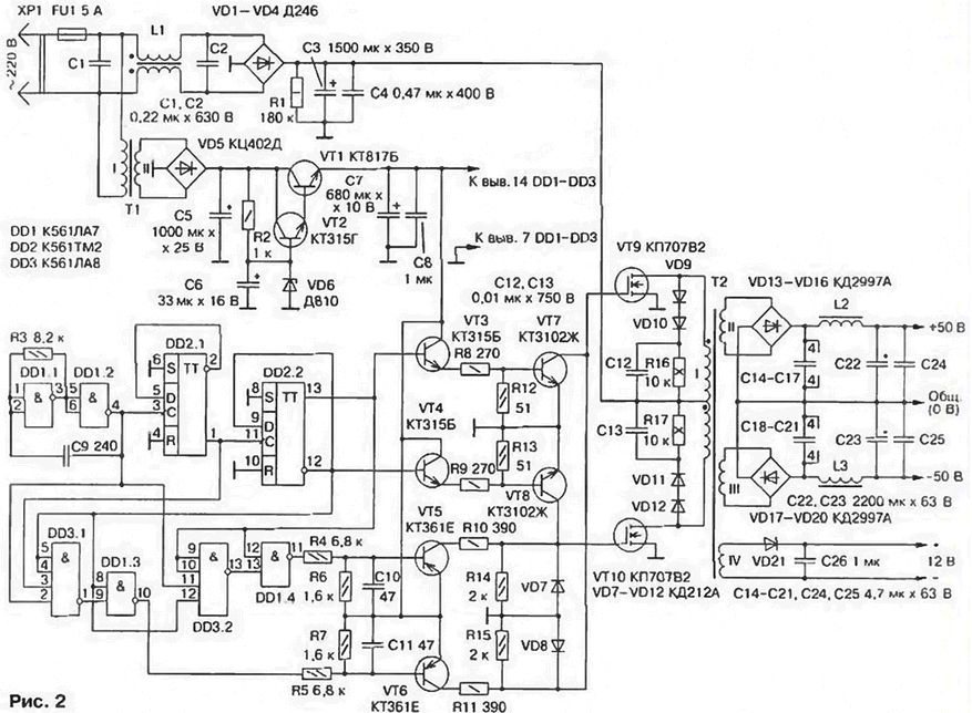
Schematic diagram of the UPS shown in Fig. 2. As can be seen, with this Converter external excitation without stabilize the output voltage. At the input device included high-pass filter C1L1C2 to prevent interference in the network. After the mains voltage is rectified by a diode bridge VD1 - VD4. ripple smoothing capacitor C3. The rectified DC voltage (about 310 In) used to power high-frequency transducer.

The Converter is implemented on chips DD1-DD3. Eats it from a separate stable source consisting of step-down transformer T1. rectifier VD5 and voltage regulator on transistors VT1, VT2 and the Zener diode VD6. On the elements of the DDI. 1. DD1.2 assembled the master oscillator generates pulses with a repetition rate of about 360 kHz. Followed by a frequency divider 4, which is made on the triggers circuit DD2.
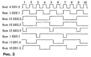
Using elements DD3.1, DD3.2 creates additional pause between the pulses. The pause is not that other, as a logic level 0 at the outputs these elements appear in the presence of level 1 at the outputs of DDI element.2 and triggers DD2.1 and DD2.2 (Fig. 3). Voltage low level output DD3.1 (DD3.2) blocks DD1.3 (DD1.4) in the "closed" state when the output - level logical 1).

The pause duration is equal to 1/3 of the pulse duration (Fig. 3, the stress-strain diagrams the conclusions 1 DD3.1 and 13 DD3.2), which is enough to close key of the transistor. From the outputs of the elements DD1.3 and DD1 .4 finally formed the pulses arrive at the transistor switches (VT5. VT6), which through resistors R10, R11 powerful operate the gates of field-effect transistors VT9, VT10.
Pulses with direct and inverse outputs of the trigger DD2.2 go to the inputs devices, transistors VT3. VT4. VT7. VT8. Opening alternately, VT3 and VT7. VT4 and VT8 create conditions for rapid discharge of the input the capacitances of the switching transistors VT9, VT10. ie quick closing. And, as can be seen from Fig. 3 (a plot of voltage across the terminals 12 and 13 DD2.2). VT7 and VT8 open immediately after the pulse, therefore, when any output the capacity of each transistor VT9, VT10 always manages securely closed before the second opening. If this condition is not fulfilled, through them, and consequently, through the primary winding of the transformer T2 have proceeded through current. which not only reduces the reliability and efficiency of the UPS. but it also creates bursts voltage, the amplitude of which sometimes exceeds the supply voltage the Converter.
In the circuit of transistor gates and VT9 VT10 included a relatively large resistors resistance R10 and R11.Together with the capacitance of the gates they form a lower filters h ml, reducing the level of harmonics when the lid of the keys. With the same purpose introduced elements VD9-VD12. P, R17, C12.C13
In stock circuit transistor VT9. VT10 included primary winding of the transformer T2. The rectifiers output voltage made in a bridge circuit diodes VD13 - VD20 that slightly reduces the efficiency of the device, but significantly (more than five times) reduces ripple on the output of the UPS. It is important to note that the form hesitation, almost rectangular at maximum load smoothly into the similar to a sine wave when you reduce power to 10 to 20 watts. positive affects the noise level of USC at low volume.
Rectified voltage IV winding of transformer T2 is used to power fans (see below).
The device incorporates capacitors K73-17 (C1. C2. C4). C50-17 (C3), MBM (C12. C13). K73-16 (C14-C21. C24. C25). C50-35 (C5-C7). Km (the rest). Instead specified in the scheme allowed the use of chips series C. C. Diodes D (VD1-VD4) interchangeable with any other, suitable for direct current of at least 5 A and reverse voltage not less than 350 (CDC. CDM. CDR, CDB. DB). or diode rectifier bridge with the same parameters, diodes KDA (VD13-VD20) - on CDB. CDB. Zener D (VD6) - DV. As can VT1 to use any transistors series CT, CT. as VT2-VT4 and VT5, VT6 accordingly, any of the series KT315, CT, CTS and CTC CT. CT. on place VT9, VT10 - KV, KE. Transistors CTR (VT7. VT8) replace not recommended.
The transformer T1 - TC-10-1, or any other voltage secondary winding 11... 13 V At a load current of at least 150 mA. The coil L1 line filter wound on ferrite (MNM) ring size CM,a wire ELVs-1 1,0(2x25 of turns), the transformer T2 is glued together on three rings of ferrite the same brand, but the size Chg. Winding I contains 2x42 coil wire Sew-2 1,0 (coil barely wires), winding II and III - to 7 turns (five wires sew-2 0,8), winding IV - round 2 sew-2 0.8. Between windings lay three layers of insulation of PTFE tape. Magnetic chokes L2, L3 - ferrite (NS) rods with a diameter of 6 and a length of 25 mm (the trimmers from armored core B). Coils contain 12 turns of PEV-1 1.5.
The transistor VT9. VT10 is mounted on the heat sinks with fans used for cooling microprocessors Pentium (similar nodes and from 486). Diodes VD13-VD20 fixed on the heat-allotments with an area of the surface is about 200 cm2. The cooling of the transistors of the output stage of USC on the rear wall installing the fan from the computer power supply or any another with a supply voltage of 12 V.
When installing the UPS should strive to ensure that all connections were possible in short, and in the power section to use the wire as possible section. UPS preferably enclosed in a metal shield and connect it to the output 0 output source, as shown in Fig. 4. Common wire of the power part with the screen to connect should not. Since the UPS is not equipped with a protection device against short circuit and overload, in the power supply circuit of USC must include fuses 10 A.

In establishing described the UPS is almost not necessary. It is important to correctly to stateroute half of the primary winding of transformer T2. With proper details and no errors in mounting the unit begins to work immediately after you turn in network. If necessary, the frequency Converter adjusts the selection of the resistor R3. To improve the reliability of the UPS, it is desirable to operate with USC, which are provided through the blowing fan.
Literature
Author: D. Kolganov, Kaluga


