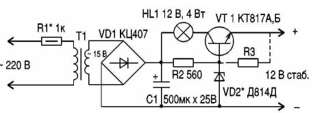
Consider a typical diagram of the power supply imported radio (see picture).

The resistor R1 reduces the pulses of current through the rectifier bridge at the time inclusion, limits the current through the primary winding of T1 when high voltage in the mains and fuses in cases with very high voltage or the occurrence of the stray circuit in the transformer. The Zener diode VD2 determines the magnitude of the output voltage (if necessary to select the instance the Zener diode when the load is switched off). An incandescent lamp is used for HL1 limitation allocated to the transistor VT1 power at rated speed and limitations of short-circuit current. If under load, the voltage decreases by more than 1 In, you should use a more powerful light (can be soldered in parallel HL1 one or two lamps garlands 13.5 In).
Radiator, cooling the transistor VT1, cut tinplate. For the best the heat dissipation plate of the heatsink should be attached to the metal of the transistor with two sides, the shape and size of the radiator should cover more space available in box. Conclusion collector bite, current
to the collector of the transistor down through the radiator. Possible current supply to the collector through the petal on the screws and pads on a printed Board through the attaching screw. Ventilation openings should provide tap heat from the lamp, so that in operation the rectifier bridge and the transistor were cold and short-circuit a little heated. On the specifics of the phone with the handset transceiver (battery) not to load the output of the block power resistor, so as not to discharge the battery when disconnecting the voltage in outlet. The principle of reliable power supply to be enabled bit resistor, even if it is known that in the scheme of phone has its diodes and lock! If after heating block table lamp when the load is switched off prove that the output voltage starts to increase, you shall be shorted the transition b-e transistor with resistor 5 ohms to 500 Ohms.
Working lamp voltage HL1 in this scheme, selected without reserve, long to short circuit lead to the burnout of the filament lamp and de-energize the circuit, and when the absence of the owners phone emergency operation not continued for months. For reliable disconnect the circuit when the stray circuit in power transformer you should ensure that during normal operation under load for 1 h the resistor R1 is warm to the touch (the plug from the mains off at the time of writing!). And the General rule is to put the PSU does not stand on a soft, that worsens ventilation, and on solid ground.
Another note: on the specifics of the phone load on the PSU the maximum at the time of the stand - pipe is laid, charging rechargeable batteries. In this regard, the development of the scheme is not intended much to suppress the ripple of the supply voltage, the more important it was to reduce the size of the device. By repeating this circuit to power other devices you may have to increase the capacitance of the capacitor C1, and also connect capacitor to the output of the stabilizer.
The shunt Zener diode capacitor of large capacity (more than thousands of picofarads) not: short-circuit output of the stabilizer of a possible breakdown of the e-b transition regulatory transistor!


