In linear power supplies, which have become "classic", the main element - mains transformer, usually a reduction, which reduces the supply voltage to the required level. About how to calculate it (select the magnetic core, to calculate the diameter of the winding wire, number of turns in the windings, etc.), go discussed in the article.
How to choose the magnetic circuit
By design magnetic circuits for network transformers divided into armored, core and toroidal and technology manufacture - on-plate (Fig. 1) and belt (Fig. 2). In Fig. 1 and 2 the designated cores: a) armor, b) - rod, V) is toroidal.
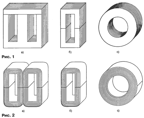
In small transformers (up to Z00 W) and average power (up to 1000 W) more use tape cores [1 ]. And among the most applicable tape rod yokes. They have several advantages compared to, for example, with amrour [2]:
However, the core magnetic inherent disadvantages:
In toroidal transformers, almost all the magnetic flux passes through the magnetic circuit, so that the leakage inductance are minimal, however, the complexity of manufacture of the windings is very high.
Based on the foregoing selectable rod tape magnetic circuit [3]. Such cores are of the following types: PL-rod tape; PLW - rod tape smallest mass; PLA - rod with belt reduced consumption of copper; PLR - rod tape least cost.
In Fig. 3 shows the designations of the dimensions of the magnetic circuit: A - width; N - the height; and the thickness of the rod; b - width of the tape; is the window width; h - height Windows; h1 is the height of the yoke.
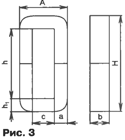
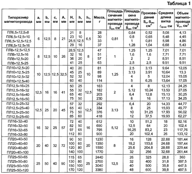
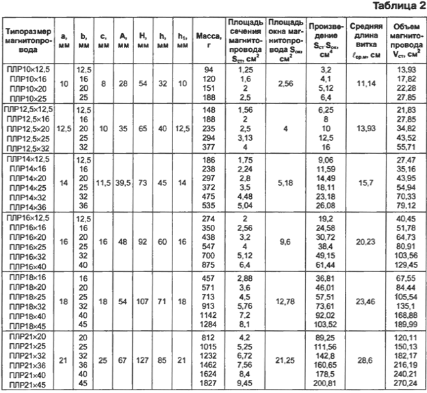
The core magnetic circuits has contracted the designation, for example, PLH 12,5x16, where SQUARE - U-shaped tape, 8 - thickness rod, a 12.5 - width, 16 - height of the window. The size of the magnetic cores PL and PLR given in table. 1 and 2.
Accommodation options coils on the yoke
The different configurations of coils on the core limbs comparable in one of the main parameters of the transformers leakage inductance, which calculate using the formula from [2]

where μ0 = 4π·10-7 Henry/m is the magnetic constant; w is the number of turns of the primary winding; HRV.about - the average length of the coil windings, cm; b - width of the windings, cm; h - the height of the winding, see This formula is obtained under the condition that the winding - cylindrical, not partitioned and arranged concentrically. The connection diagrams windings for all variants shown in Fig. 4.

Comparative calculations will hold for transformer on the yoke Plhh,5x40, having one primary and one secondary winding. To all settlement options were in the same circumstances, will adopt the thickness of the windings b = C/4 and the number of turns of the primary winding w1 = 1000.
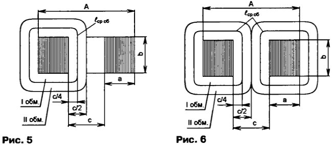
Let's consider the first option, when the primary and secondary windings are located on one terminal (Fig. 4, a). The drawing of the coil shown in Fig. 5. First, we calculate the average length of the coil windings

and then the leakage inductance of the coil of the first embodiment

In the second embodiment, the primary and secondary windings is divided into two equal parts, placed on two rods (Fig. 4, b). Each coil consists of half of the windings W1 and half of w2. The drawing of the coils shown in Fig. 6. Calculate the leakage inductance of one coil (W1 = 500), then the result will double, since the coils are the same:

Two of the primary winding in the third embodiment, are located in two coils in a variety of rods, each of which contains 1000 turns. Both the primary winding connected in parallel. The secondary winding is also available in two coils on different rods, and two cases are possible: two Polubotko with the full number windings connected in parallel (Fig. 4), or the secondary winding is divided into two Polubotko twice with a smaller number of coils connected in series (Fig. 4, g). The drawing of the coils shown in Fig. 6. In this embodiment, the leakage inductance the same as in the second embodiment: LS3 = LS2 = 2,13 mH.
It should be remembered that in the second and third embodiments, the primary and secondary windings and Polubotko should be included under that they create magnetic flows in the magnetic circuit have the same direction. In other words, the magnetic threads should be added, not subtracted. In Fig. 7, but shown wrong connection, and in Fig. 7, b - correct.

The need to respect the rules of connection of the windings and Polubotok - lack the second and third options. In addition, in the third embodiment, the total magnetic flow from the primary winding is twice more compared to others that may lead to saturation of the magnetic circuit and, as a result, the distortion of the sinusoidal voltage forms. Therefore, to apply a third option-breaker in practice carefully.
In the fourth embodiment, the primary winding is located entirely on one rod of the magnetic circuit, and the secondary on the other (Fig. 4, d). The drawing of the coils shown in Fig. 8. Since the windings are not arranged concentrically to calculate leakage inductance will use the formula from [2]:

where b = C/4 - thickness of the windings, cm; RVN = EO/(2π) is the outer radius of the winding, cm; EO = 2A+2b+2πb - outer length of the coil winding, see Compute the length of the outer loop and an outer radius of coil: = 6.5 cm; RVN = 1,04 see Substituting the calculated the values in the formula to calculate the leakage inductance, get LS4 = 88,2 inst.
In addition to the four there are plenty of other options for the location the windings on the cores of the magnetic circuit, however, in all other cases the leakage inductance is greater than the second and third options.
Analyzing the results, we can draw the following conclusions:
Therefore, in the manufacture of small power transformers should choose circuit of the connection and arrangement of the windings, are considered in the second embodiment. Secondary Polubotko can be joined together in series, if necessary to obtain a higher output voltage, and in parallel, if required higher output current.
Summary of magnetic materials
So far we did not take into account losses in a real transformer, which add up the losses in the magnetic circuit on eddy current and magnetization reversal (hysteresis): in the calculations take into account the power losses in the steel of the PCT, and loss in the windings as the power loss in the copper of the RM. So, the total power losses in the transformer is equal to:
P∑ = PCT + RM = RV.t + RG + RM,
where RV.t - power losses eddy current; WG - power loss due to hysteresis.
To reduce the steel is subjected to heat treatment - remove carbon and doped - added silicon, aluminum, copper and other elements. This increases permeability, coercive force decreases and, consequently, the loss of the hysteresis. In addition, the steel is subjected to cold or hot rolling to obtain the necessary patterns (textures).
Depending on the content of alloying elements, structural state, magnetic properties of the steel are labeled by four-digit numbers, for example, 3412.
The first digit indicates the class of electrical steel structural condition and class rolling: 1 - hot rolled isotropic; 2 - cold-rolled isotropic; 3 cold - rolled anisotropic with hip texture.
The second number is the percentage of silicon: 0 - non-alloy steel total the weight of the alloying elements is not more than 0.5 %; 1 - alloyed with a total mass over 0.5 but not more than 0,8 %; 2 - 0,8...1,8 %; 3 - 1,8...2,8 %; 4 - 2,8...3,8 %; 5 - 3,8 4,8...%.
The third figure group on the main normalized characteristic (specific losses and magnetic induction): 0 - specific losses in magnetic induction at 1.7 T 50 Hz (Pij/so); 1 - loss magnetic induction 1.5 T at a frequency of 50 Hz (P1,5/50); 2 - at the induction of 1 T at a frequency of 400 Hz (P1/400); 6 - induction in weak magnetic fields at a tension of 0.4 A/m (B0,4); 7 - induction in medium magnetic field at an intensity of 10 A/m (B10) or 5 A/m (B5).
The first three digits indicate the type of electrical steel.
The fourth digit sequence number type of steel.
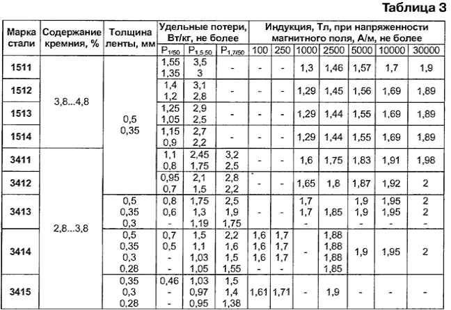
The magnetic cores of transformers for home appliances are made of cold rolled steel grades of texture 3411-3415 [3] with a normalized specific losses in magnetic induction 1.5 T at a frequency of 50 Hz and specific resistance 60·10-8 Ω·m. the Parameters of some grades of electrical steel given in table. 3.
Cold-rolled electrical steel has a higher magnetic characteristics. In addition, a smoother surface can increase the fill factor of the volume of the magnetic core (FTC) to 98 % [4].
Initial data for calculation of transformer
Calculate transformer having a primary and two identical secondary windings, with the following parameters: the effective (RMS) voltage of the primary winding U1 = 220; effective (RMS) voltage of the secondary winding U2 = U3 = 24 V;
effective (current) current of the secondary winding l2 = I3 = 2A. Frequency network voltage f = 50 Hz.
The transformation ratio is the ratio of the voltage to the primary voltage on open (EMF) in the secondary winding. In this case we ignore the error, arise from differences in the EMF of the voltage on the primary winding:

where w1 and w2 is the number of turns, respectively, the primary and secondary windings; E1 and E2 - EMF of the primary and secondary windings.
The current in the primary winding is equal to:

Overall power of the transformer is equal to:

In the process of calculation necessary to determine the size of the magnetic circuit, the number of turns all windings, diameter and the approximate length of the winding wire, power loss, full capacity of the transformer, efficiency, maximum dimensions and weight.
The calculation of the magnetic circuit of the transformer
The method of calculation of dimensions and other parameters are taken mainly from [1].
First, we calculate the product of the cross-sectional area of the rod to the square the Windows of the magnetic circuit. The rod is called the phase of the magnetic circuit (axbxh) hosting reel:

where b is magnetic induction, T; j is the current density in the windings, And/mm2; η - efficiency transformer, n is the number of cores of the magnetic circuit; the COP - coefficient of filling cross-section of the magnetic steel; km - the fill factor of the window of the magnetic circuit copper.
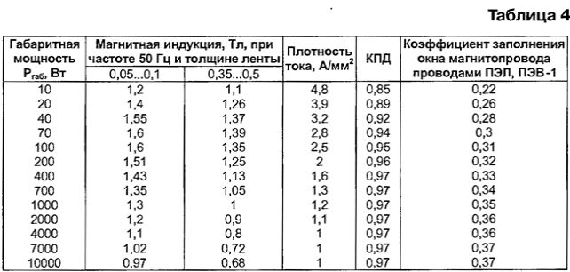
Recommended values of magnetic induction and average values of current density, efficiency and the fill factor of the window for the frequency f is 50 Hz are shown in table. 4.
The fill factor of the cross section of the magnetic circuit for steels 3411-3415 equal 0,97 0,95...for steels 1511-1514 - 0,89...0,93.
For the calculation accept In = 1,35 T; j = 2.5 A/mm2; η = 0,95; COP = 0,96; km = 0,31; n = 2:

The thickness of the core of the magnetic circuit is calculated by the formula

Suitable magnetic core is chosen according to the table. 1 and 2. When choosing, you should strive to ensure that the cross section of the magnetic core was close to a square, as in this if the flow rate of the winding wire is minimal.
The width of the magnetic tape is calculated by the formula

Select the magnetic Plrh, whose a - 1.8 cm; b = 2.5 cm; h = 7.1 cm;

The calculation of the transformer windings
Calculate the EMF at one loop by the formula

Calculate approximately the voltage drop across the windings:

Then calculate the number of turns of the primary winding:

secondary winding:

Calculate the diameter of the winding wire without insulation by the formula

Substituting numerical values, we obtain the wire diameter of the primary:

and secondary windings:

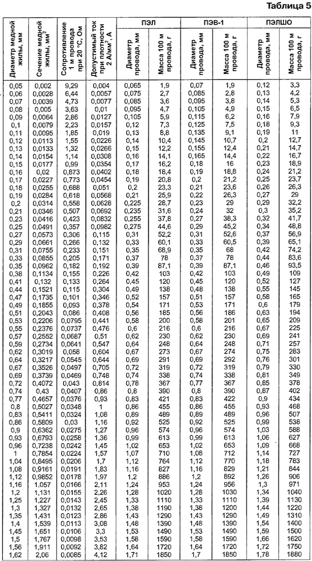
On table. 5 choose the brand and the diameter of the winding wire in isolation [5]: the primary winding - PEL or sew-1 di = 0,52 mm; secondary - PEL or sew-1 d2 = d3 = 1,07 mm.
Specify the number of turns of the windings. To do this, first check the voltage drop on windings:

Calculate the average length of the coil, using Fig. 5 or 6:

and then the length of wire in the windings:

More accurate values of the voltage drop across the windings is equal to:

Given these values we calculate the number of turns of the primary:

and secondary windings:

Calculate the mass of the wires:

where m1 and m2 are linear mass of wires, respectively, primary and secondary the windings of the table. 5.
The mass of the magnetic circuit defined by table. 2: Mm = 713 G.
Transformer weight excluding the weight of the mountings is equal to M = 288+2-165+713 = 1331 g. the Maximum dimensions: (B+C)x(A+C)HN = 43x72x107 Coefficient mm. the transformation k = W1/W2 = 1640/192 = 8,54.
Calculation of power loss
The losses in the magnetic circuit is equal to:

where is Rud - specific losses in the magnetic core of Fig. 3. Suppose that the yoke is made of steel tape 3413 0.35 mm thick, then on the table. 3 find that specific losses in the magnetic circuit is equal to 1.3 W/kg. Accordingly, the losses in the magnetic core PCT = 0,713-1,3 = 0,93 W.
Losses in the winding - on active resistance of the wires is calculate by the formula

where r1, r2 is the resistance, respectively, primary and secondary the windings, I'1 - current of the primary winding, with the losses:

where g1m, GM - linear resistance of the wires, respectively, primary and the secondary winding of the table. 5.
Recalculate the current of the secondary winding of the current of the primary winding:

The current of the primary winding with the number of casualties equal to:

where η = 0,95 - efficiency of the transformer of Fig. 4 for 100 watts. Losses in the windings are equal:

Full power transformer with losses equal to:

Efficiency of the transformer will calculate according to the formula

Transformer manufacture
To make the transformer will be the second embodiment discussed above. The arrangement of coils shown in Fig. 6. For this purpose it is necessary to make two coils, each of which contains half of the turns and each of purvinas secondary winding: w'1 = 820 turns of wire PEL (or sew-1) diameter of 0.52 mm; w'2=w'3= 96 turns of wire PEL (or sew-1) diameter of 1.07 mm.
Because the transformer has a small capacity and size, the coil can to make a frameless. Thickness of coil b ≤ C/2 = 9 mm, its height hK ≤ 71 mm.
The number of turns in the layer of the primary winding

the number of layers

The number of turns in the layer of the secondary winding

the number of layers

Winding is wound on a wooden frame, made in strict accordance with the size of the area of the magnetic circuit, which will be located coil (18x25x71 mm). To the ends of the mandrel is attached to the cheeks.
Despite the fact that the winding wire is covered with enamel insulation and therefore have a high electrical strength, usually between the winding layers navigate further, for example, paper insulation. Most often for isolate the windings from the core and between a transformer used paper thickness 0.1 mm. Calculate the maximum voltage between two adjacent layers of the primary winding

Since the voltage between the layers is small, additional insulation can lay through the layer or make it more subtle, for example, use condenser paper. Between the primary and secondary should be placed the shielding winding - one open-loop coil of thin copper foil or a single layer winding wire, which prevents interference from the network in secondary winding and Vice versa.
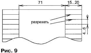
First, the mandrel is wrapped with three layers of paper tape (Fig. 9), petals tape glued to the cheeks. Then is wound the primary winding, each paving a layer of insulation. Between primary and secondary windings of the shielding lay two layers of insulation. The total thickness of the manufactured coils does not exceed 8 mm.
Check transformer
The assembled transformer is first checked at idle without load. When mains voltage of 220 V, the current in the primary winding

secondary winding voltage

Secondary winding voltage can be accurately measured only with voltmeter high input impedance. Finally, the voltage on the secondary windings the transformer is measured at rated load.
Literature
Author: V. Pershin, Ilyichevsk, Odessa region, Ukraine


