


")

Absolutely not all power sources can provide good protection for your equipment which needs to be powered from low voltage. It may happen that when the closure (even fairly short) output voltage transition TBE regulating transistor can authority", well if the "authorit" i.e. the voltage at the output of the PSU will be lost, but if the transition of the SE will close then…goodbye my KENWOOD, because all the voltage that is to be input to the stabilizer will change and the output.
Want to offer a relatively simple but reliable enough power source, which is free from all those hassles mentioned above and that can be useful to any Amateur radio operator, motorist, and maybe someone else. Using it can be powered radios, power amplifiers, high and low frequency, etc.
Main features:
- the output voltage from 1.3 to 37 In;
- the maximum load current is 15 A;
- current protection of the load in excess of 15 A ;
- surge protection when increasing the output voltage higher than 15 V and 30 V;
- the response time protection:
(a) current - not more than 15 MS;
b) overvoltage - no more than 8 MS. - the amplitude of the ripple of the output voltage, load current 15 A, is less than 0.3 V.
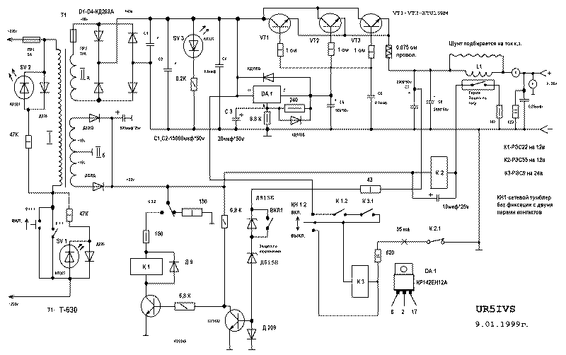
The principle of operation
When pressing the push-button switch CN utility voltage to the transformer T1 and included relays K3 and K1, the latter of which blocks the contacts KN.1 their contacts K1.1 Contacts remain closed as long till it works relay K2 or until such time as the output voltage remains within the established norm. The toggle switch on 1 is for installation of this norm, i.e. if the contacts of this switch are closed the surge protection will increase the output voltage above 15, but if the contacts are open, the surge protection will increase the output voltage above 30 V. of Course You can make these other limits, it is enough instead of two (or one) of the Zener DE to put other i.e. to the desired voltage stabilization. If the current at the output of the PSU will exceed the established norm, then work the switch which will activate the relay K2, and K2 will disconnect the power K3, K1 by the locking contacts will switch off the transformer T1, the led turns on (red glow) SV1, who will speak about the power is off or a worn-out one of the defenses.
Transistors CT and KT3102 executed surge protection. Transistors VT1-VT3 to be installed on the radiator surface area of at least 800-1000 cm2, it is desirable to ensure good thermal contact between the heat sink and transistors with heat-conducting paste. Resistance which are in the circuits of the windings of the relay (because the resistance of the winding of the relay is widely (see in any "normal" directory)) should be selected so that the current supply relay exceeded the minimum current (specified in either the "normal" directory) triggering on average 50%, otherwise deluhi may not work. Deluhi -22 four changeover contacts, so three (in the circuit of the primary winding of the transformer) is better connected in parallel. Adjusting the stabilizing voltage is a variable resistor of 6.8 K, which is conventionally designated 8 foot KREN. The transformer T1 any, of a power less than 500 W (I SHL-630), which can provide a voltage of 28 V At a load current of 20 A. Winding to supply the protection modules can be wound and thin enough wire is provided (just in case) At 0.5 A. KREN need to tie a small radiator surface area of at least 10 cm2, because it may overheat from basic loads (although not large). Diodes D1-D4 to be installed on the radiator area of 100 cm2, and even better if you put ready on the bridge using a direct current of at least 20 and mounted to a common radiator together with transistors. Coil L1 is wound on the rim having a diameter slightly greater than that of the reed switch and contains 3-5 turns of wire with a diameter of 1.5 mm, then the switch is inserted into the coil and is fixed. The shunt is a short thick (diametra,5-2 mm) pigtail which limits the current flowing through the coil L1, shortening his or extending and moving in the opposite direction from the magnetic switch can be calibrated current protection operation. At sufficiently high currents of the coil and the shunt can not do, and be positioned perpendicular to the reed switch wire or track. Led green glow SV2 indicates the power supply, SV3 can not be put.
Optionally, anyone can modify the commutation circuit of deluhi K1, for example commuting not only the primary winding and the output is stabilized voltage (in this embodiment, when an overvoltage is provided by the instantaneous disconnection of the load from the power source because the electrolytic capacitors of large capacity may not have time to discharge), it is better to take a more powerful relay.
Lastly, I want to draw Your attention to the information published in the magazine "Radio" No. 8, 1993, pp. 41-42, which describes the chip KREN with its inclusion. I will not say it correctly or not, but in this version I threw about a dozen chips Recalling their marriage, however, it is unlikely that ten out of ten will get rejected. Why I included this stabilizer as an LM317T. By the way, CREA can be replaced by its counterpart (even on inclusion) LM317T.
The diagram of the power supply with high resolution (98 KB)
Author: M. Denisenko (UR5IVS), Donetsk region, Makeevka; Publication: N. Bolshakov, rf.atnn.ru