Unlike other such structures, we offer our readers the power supply antenna the amplifier does not contain its own switch and starts working at the same time with the inclusion of the TV.
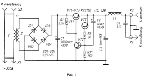
This device (Fig. 1), being a source of stabilized voltage 10...12 V At load current up to 20 mA, suitable for power relatively simple TV antenna amplifiers and converters UHF. A distinctive feature of the unit is that it instead classic transformer, step-down voltage used the current transformer T1, the primary winding of which is connected in series with primary power circuit TV.

The current transformer on the basis of which to build, for example, indicators consumed power, operates as follows. Flowing through the primary winding of the current consumed a TV, it creates a voltage drop 2...3 V. It does not exceed 1...2% the mains voltage and, of course, does not affect the normal operation TV. An alternating voltage of the secondary winding of the transformer is rectified bridge VD1 - VD4, and pulsation of the rectified current is smoothed by the capacitor C1.
Transistors VT1-VT3 assembled the compensation voltage stabilizer.
With its release the stabilized voltage + 10...12 through the inductor L1 serves on the nest X3 which is connected to the Central wire lead-in cable antenna placed on it by the amplifier. Plug X4 is connected to the antenna input TV. The mains plug of the TV is connected to jacks x2 device and plug X1 to your network.
The device can be applied to the transistors CTV - CTE, CTB or from the KT3102 with alphabetic indices A, B; a diode - rectifying any (better germanium). Capacitor C1 - C50-16, C2 and C3 - C50-6, C4 - KD, KG, KLS. The inductor L1 type. DM-inductance of 0.1 to 20...50 μg or improvised, performed on ring the magnetic core diameter 5...10 mm ferrite 1000...N; winding comprises 30 turns of wire sew-2 0,1...0,15.
Current transformer wound on the magnetic core subscriber loudspeaker, the magnetic core transformers USC radio "Climber-407" or similar. The first secondary winding is wound, which contains 1000 turns the PEV-2 to 0.1. Then, wrapping it with a layer of good insulation, wind the primary winding, the number of turns of which depends on the power consumption of TV. Just for television, which consumes a power of 60 W, the primary the windings must contain about 150 turns of wire sew-2 to 0.4. For TV with more power the number of turns of this winding is reduced, and the diameter used for wire proportional increase. The final number of of turns of the primary winding of the transformer is set empirically at establishing the device.
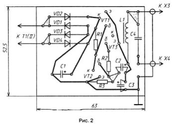
All the details of the power supply, in addition to the plug connector and the transformer, mounted on the circuit Board of foiled fiberglass (Fig. 2). Cost and the transformer is placed in the housing of suitable size of insulating material. The x2 socket and socket X3 is mounted on the front wall of the housing. The conductor connecting the charge socket X3, must be of a minimum length - not more than 20...30 mm. Finished block power feature on the back wall near the TV antenna Jack, hooking its a hook from a wire for the vent, or directly on a TV stand.

Testing and adjustment of power supply is carried out in this order. Its output is connected the dummy load (resistor) resistance of 680 Ohms, and the capacitor C1 serves the voltage from the external power source 15...20 V. Then the selection of the resistor R3 is set the output of the stabilizer (at the capacitor C3) voltage 10...12 V. Further to the Board solder the conductors of the secondary winding of the transformer, and a power supply with the connected TV power cord connected to the mains. After the TV was turned on, the voltage at the capacitor C1 should be in the range of 15...18 V. this can be Achieved appropriate selection of the number of turns of the primary winding of the transformer.
The described variant of the block power antenna amplifier may be universal, i.e. suitable for TVs with different power, if the primary winding current transformer to comply with taps and switch them depending on model TV.
In the case of joint works of such power supply to antenna amplifier need in the inductor L2 and the capacitor C9 is its decoupling node power disappears.
If noise appears in the form slowly moving across the screen horizontal stripes, diodes the rectifier bridge is necessary shall be shorted ceramic capacitors in a few thousand picofarads.
Author: I. Nechaev


