The old film-viewing device, which is not to be applied by direct purpose, it is easy to alter in regulated power supply with protection against overloads and short circuits. For this purpose, from the film-viewing device use case with transformer and power cord. Instead of a reflector and bracket with a socket and lamp set fee with the rectifier and the voltage regulator. Instead the lens can be set voltmeter to monitor the voltage at the output source.
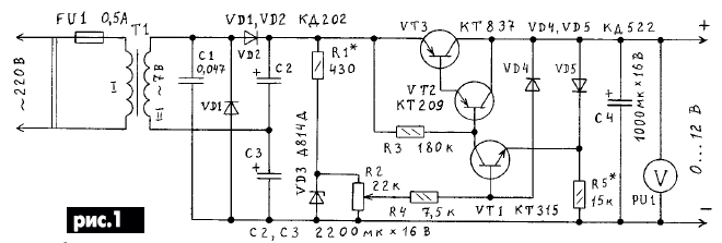
The diagram of the power supply shown in Fig.1 .

It consists of a step-down transformer T1 doubler rectifier voltage (VD1, VD2, C2, C3) and stabilizer transistors VT1 VT3...with adjustable output voltage that can be to change from 0 to 12 V with a load current to 0.7 A. the Stabilizer is designed to the basis of the devices described in [1,2]. The reference voltage is removed from the Zener diode VD3 and forth with the engine resistor R2 (voltage regulator) through the resistor R4 is supplied to the base of transistor VT1, which controls the transistors VT2 and VT3. Diode VD4 and VD5 protect the regulator against overload and short circuit output.
The current at which the protection is triggered, depends on the magnitude of the resistance of the resistor R5. While the load current does not exceed some threshold value, diode VD5 is open and forms with the resistor R5 of the voltage divider. Diode VD4 thus closed and the operation of the stabilizer has no effect. In short the circuit or excessive consumption current of the diode VD4 and VD5 connect with negative conductor through a low resistance load. Diode VD5 is closed, and diode VD4, on the contrary, at this time opens and connects the base of transistor VT1 to the negative wire. All transistors in this case is closed and the current through the load drops to a few milliamps. Resistors R3 and R4 reduce the current short circuit. The capacitor C1 serves to suppress interference from penetrating the network.
Also indicated in the diagram, the power supply you can use the following details: transistors CT, KT3102 (VT1); CT, CT, CT (VT2); CT, CT (VT3); diodes D, D243 (VD1, VD2); CD, D, CD and other low-power silicon (VD4, VD5); Zener CSA or more other series Zener with a total voltage stabilization about 12 In (VD3); variable the resistor 10...100 kω (R2); the resistors 150 200... ohms (R3); 5,1...10 kOhm (R4); capacitor of 0.01...0.1 μf (C1).
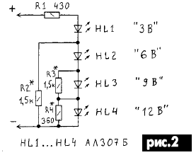
Instead voltmeter PU1 to the output of the power supply can be connected led indicator voltage (Fig.2).

This indicator allows you to set the output of block voltage with an accuracy of 0.2 In, and can also serve as an overload indicator or output short circuit.
The transistor VT3 is set on the device. Between the transistor VT3 and the body should be placed a metal plate of a thickness of 3...5 mm and dimensions about 30 x 50 mm. This will increase the area of thermal contact of the transistor with the corps. The output of the power supply, voltmeter and a variable resistor located on the front wall of the housing.
Adjustment of the stabilizer is reduced to the selection of the resistors R1 and R5. Selecting resistor R1 sets the current through the Zener diode VD3, equal to 15 mA, and resistor R5 - current protection operation.
Literature
Author: L. D. Bogoslavets, Cherkasy region


