


")

The unit is designed to power the kit Amateur radio equipment, comprising from LW and УSW transceivers with output power up to 100 watts. The basis of his circuit the decision was taken by the UA1ZH and added protection devices-current and voltage (Fig. 1).
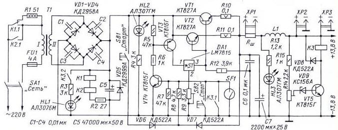
Fig. 1
On closure of switch SA1 voltage supplied to the primary winding the transformer T1 via the resistor R1. When the voltage at the output of the rectifier VD1-VD4 reaches the trigger voltage of the relays K1 and K2, via shutting the relay contacts K1.1 and K2.1 to the winding I of the transformer T1 will be served full the mains voltage. Such a stepped transformer limits the initial inrush current through the rectifier diodes, loaded large capacity capacitor C5. The time delay of tens of milliseconds. Thus stabilizer PSU does not work and does not heat the air in vain. Led HL2 signals the inclusion of standby power source.
After clicking the button SB1 "Start" rectified voltage +24 V through the diode VD6 and divider formed by resistors R7R8. will go to the base of transistor VT4, it will open and then opens the transistor VT3. With the collector of the transistor VT3 the voltage received at the input circuit DA1, and with its release on base regulating transistors VT1, VT2. The regulator will switch to the operation mode, and the output voltage appears, what will signal the led HL3. The output voltage across the diode VD7 will arrive at the base of the transistor VT4, holding it in the open position after releasing the button SB1.
The stabilizer off occurs when a short push on the button SB2 "Stop." The transistor VT4 is closed and, in turn, will close the transistor VT3. The voltage on the chip DA1 is not received, and the transistors VT1, VT2 there will also be closed. The HL3 led will go out.
Sensor protection BP against excess current consumption serves as a choke coil L1, connected in series with the load. Inside the coil is placed a reed switch SF1. On with the increase in the current flowing through omuku increasing the magnetic field, which causes the actuation of the reed switch contacts included parallel to the button SB2 "Stop". At the output of the power supply include a threshold protection device for voltage performed on the transistor VT5, the Zener diode VD9 and relay circuit. If the output voltage of the stabilizer for any reason exceeds the voltage protection trip (set trimmer R14), turns on relay K3 and their contacts K3.1 causes the base of transistor VT4 on common wire source, translating the AVR in standby mode. At the same time via relay short circuit.2 power on led HL1, signaling the overload.
The performance of the system is sufficient to protect fueled equipment.
The device is equipped with measuring instruments - ammeter and voltmeter ( the scheme not shown) that are connected to plug connectors HR and XP2 respectively. The connector HRS is designed to connect the device for blowing transistors VT1, VT2 - fans, temperature sensors and controller Board speed.
The output of the transformer T1 is 300…400 watts. AC voltage at the secondary the winding - about 18 In load current of 20 A. the rectifier Diodes VD1-VD4 established via a thermally conducting paste KPT-8 on the heat sink dimensions mm 155x50 with the height of the ribs 25. the Transistors VT1 and VT2 are installed on a heat sink with dimensions 100x80 and height of the ribs 30 mm (an area of not less than 1200 cm2). Heat sinks are set opposed - parallel to each other at a distance of 80 mm. They turned edges inside and interconnected (covered) duralumin the plate forming the tunnel. At the end of this structure is fixed computer fan dimensions 80 80 mm. the Sensor system of fixed airflow through the thermal paste on one of the sinks.
A second fan installed on the side of the case PSU and works on injection air into the case. initially, the fans run at low speed. When the heatsink temperature +50°C maximum momentum, however, they can to regulate. The fans and Board speed control is borrowed from computer PSUs are used In the design ready digital modules: SVH0001R - voltmeter, SAH0003R-50 - ammeter company Ekits. They are installed on a removable the front panel of the PSU and connected according to the diagrams, recommended by the manufacturer. The wires from the modules, equipped with miniature connectors. On wire put ferrite rings 2000nn diameter of 10 mm to reduce interference from the work of microcontrollers.
Some elements of the stabilizer is mounted on the circuit Board from foiled fiberglass. The drawing Board and the elements in it is shown in Fig. 2.
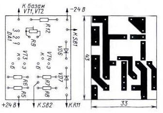
Fig. 2
The capacitor C5 is composed of ten capacitors C50-35 4700 UF 50 V, connected in parallel. The meter shunt current (VSH) - industrial 75 SHS HOST-61 0,5 (50, 75 mV).
Relays K1 and K2 - OMRON (automotive) operating voltage 12 V, their contacts designed for switching current 10 A at AC 240 V. To reduce sparking when switching the relay contacts should shall be shorted capacitors capacitance …0,1 0,01 µf rated voltage not less than 400 V. the Relay KZ - on RES the operating voltage of 12 V.
The PSU is mounted in the computer housing micro-ATX. Instead The USB ports under the cover on the front panel hosted screw terminals - terminals for connect harness the power of the transceiver(s).
The establishment of the power source is to install a trimming resistor R9 voltage 13.8 V at the output of the stabilizer and setting protection levels actuation. Current is the selection of the number of turns of the coil L1 (the author of four round the PEV-2 with a diameter of 2.5 mm) and the fixing of the reed switch. Reed, by the way, has some noticeable hysteresis And voltage - selection of the Zener diode VD9 (roughly) and adjustment of the resistor R14 is (exactly).
Author: Inozemtsev D.