As you know, in a standard USB connector provides power for external devices with voltage of 5 V at a current of about 500 mA. Unfortunately, for most portable equipment requires 9 or 12 V. the Emergence of specialized chip voltage converters greatly simplifies the task of creating the PSU with the required parameters.
In Fig. 8.1 shows a diagram of a variant of the power supply, allowing you to get 9 or 12 V power 5 V USB port.
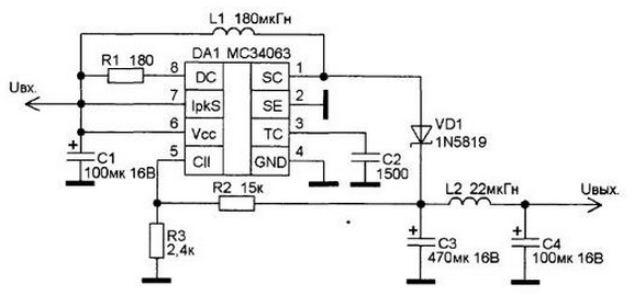
Fig. 8.1
The basis of the scheme is a specialized chip MS (Russian equivalent - CEU). Chip MS is a control circuit of DC/DC-Converter. It contains a temperature-compensated reference voltage source (ION), the comparator generator with adjustable duty cycle, the circuit current limitation, the output stage and high-current key.
This chip is specifically designed for use in step-up, step-down and inverting converters with a minimum number of elements.
The voltage obtained booster Converter is determined by two the resistors R2 and R3.
Selection of resistors is that the comparator input (pin 5) must be a voltage of 1.25 V. the calculation of the resistor values for the circuit in Fig. 8.1 can be produced using simple formula:

Setting the output voltage and the value of the resistor R3, one can easily compute the value of the resistor R2.
The picture of the PCB of the inverter shown in Fig. 8.2, the scheme of arrangement elements in Fig. 8.3.
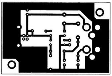
Fig. 8.2
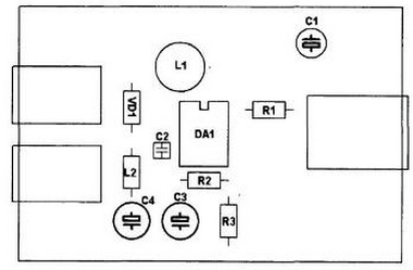
Fig. 8.3
Since the output voltage is set resistor divider can to improve the scheme by adding a switch that allows you to get different voltages as needed. Version Converter on two output voltage (9 and 12) is shown in Fig. 8.4.
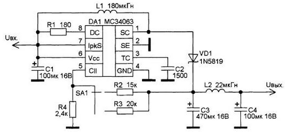
Fig. 8.4
The printed circuit Board pattern Converter shown in Fig. 8.5, the arrangement of the elements in Fig. 8.6.
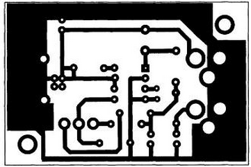
Fig. 8.5
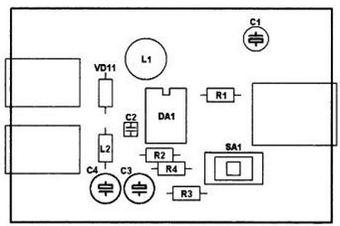
Fig. 8.6
The resistors used in the device - any power from 0.125 to 0.5 W, type MLT or C2-29, non-polar capacitors-type KD, KM, K10-17, etc Electrolytic capacitors - type C50-29, K50-35 or similar. The inductance of the inductor L1 is 120-180 µh, with power dissipation of 200 mW. As the inductor L2 is used integrated inductance type ES or similar. The inductance of the inductor 10 to 33 µh.
Authors: S. R. Bashirov Bashirov A. S.


