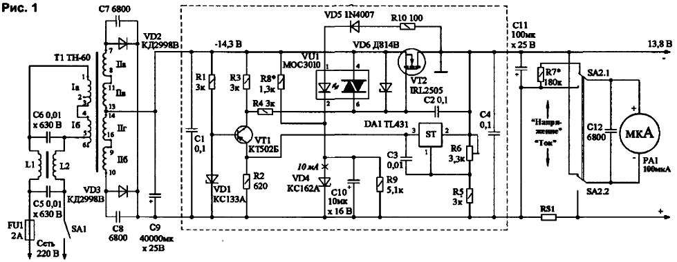
The proposed power supply (Fig.1) is designed to work with a powerful low-voltage loads, such as with УSW FM radio stations, having an output power of 50 W ("Alinco DR-130"). Its advantages include low drop the voltage on the rectifier diodes and the control transistor [1] and the presence of protection against short-circuit [2, 3].

The voltage through the closed contacts of switch SA1. fuse FU1 and mains filter C5-L1-L2-C6 is supplied to the winding I of transformer T1. With the secondary winding II T1 having a drain from the middle of the positive half voltage through the rectifier diodes VD2 and VD3 act on condenser smoothing filter S9.
To filter a linear regulator connected with a regulating element for field the transistor (PT) VT2. To control the transistor voltage required 2,5 .3.. In, so there is no need for a separate rectifier for power the control circuitry MO, as for example, in [4]. To increase the coefficient stabilization stabilizer applied "adjustable Zener diode" - chip DA1 TL431 (domestic analogue - KREN). Transistor VT1 - matching, a Zener diode to stabilize the voltage VD1 in its base circuit. The output voltage the stabilizer can be calculated by the approximate formula
The regulator operates as follows. For example, if the load is connected the output voltage is decreased. Then decreases the voltage at the middle point divider R5-R6, DA1 chip (like a parallel stabilizer) consumes less current, and the load (resistor R2) reduces the voltage drop. This resistor is in the emitter circuit of the transistor VT2 and, since the voltage at its base is stabilized by Zener diode VD1. the transistor opens stronger, providing an increase in the voltage of the gate of the regulating transistor VT2. Last more open and compensates for the voltage drop at the output the stabilizer. This ensures stabilization of the output voltage. The output voltage is set by resistor R6. The Zener diode VD6. included between the source and the gate VT2. serves to protect PT from impermissibly voltage gate-source and is a required element in stabilizers with an input voltage of 15 V and above.
This power unit is a variant of the device described in [3]. Here used the same regulator with protection, but excluded the two-stage BP and start protection circuit against overvoltage. In BP added measuring the output voltage and the load current at needle device RA1 (head of the microammeter M2001 with current full deflection of 100 μa), the additional resistor R7, the shunt RS1, suppression capacitor C12 and the switch SA2 ("Voltage/current"). Since the operating temperature PT BP in this lightweight, FRI applied type IRF2505 in the case of to-220, which has a higher thermal resistance, than IRF2505S [3].
Transformer TN-60 occurs in two modifications: powered by network 220 In combination with the primary winding for connecting the transformer to the network stresses 110.127. 220 and 237 V. the Connection of windings T1 in Fig.1 shown for strain 237 V. This is done to reduce the no-load current T1, reduce stray fields and heating of the transformer, increasing efficiency. In networks with low voltage (about 220) is connected between the pins 2 and 4 the primary windings. Instead of the transformer TN-60 you can apply TH-61.
To reduce the "drawdown" load voltage applied to the rectifier circuit with an average point using diodes Shot-Ki. the inclusion of the windings T1 optimized for uniform distribution of load on them. Installation power circuits PSU is made by cable with a conductor cross-section not less than 1 mm2. Diodes The Schottky installed without gaskets on a radiator from an old computer monitor (aluminum plate), which with the help of available pins are soldered in Pato, which contains a set of capacitors C9 (4 PCs 10000 mcfh In). Shunt RS1 to measure the load current is the "positive" wire connecting the bus on the PCB conclusions from C9 to the connecting terminals of the load.
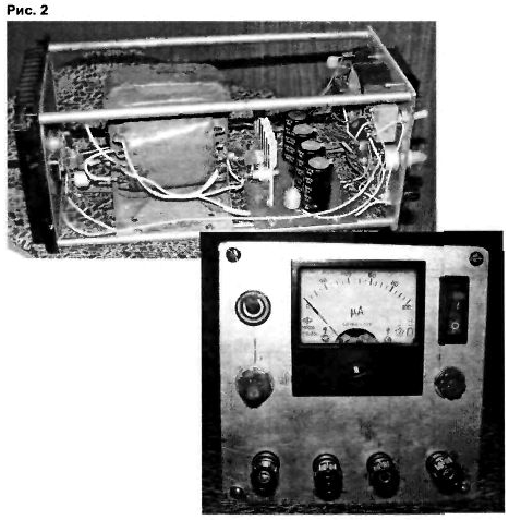
Structurally, the PSU is very simple (Fig.2).

The rear wall is radiator, front wall (panel) is the same length and width of the piece thick duralumin 4 tAtA. The walls 4 are bonded together by pins 07 mm steel. They have end openings with M4 thread. To the lower pins screwed (4 screws M4) shelf from dural thickness of 2 mm according to the size of the transformer. So the same way attached plate of one-sided glass fiberglass 1.5 mm thick. on which are mounted capacitors C9 and radiator with diodes VD2, VD3. The front panel has two pairs of output terminals (parallel), the measuring head RA1. the regulator output voltage R6, switch current/voltage SA2. the FU1 fuse holder and switch power SA1. The case for BP (U-bracket) can be bent mild steel or to collect from the individual panels. The radiator under SU (123x123x20 mm) applied ready, from the power of old УSW radio "Kama-R". The length of the fastening studs - 260 mm, but may be reduced to 200 mm with tighter editing. Sizes plates: duralumin under T1 - 117,5x90x2 mm of fiberglass - 117.5x80x1,5 mm.
Coil line filter L1. L2 are wound with flat wire network cord ferrite core (with permeability of 400.. .N) from magnetic antenna radio (before filling). Rod length - 160...180 mm, diameter - 8. ..10 mm To the terminals of the coils are soldered type capacitors K73-17, designed for a working the voltage of at least 500 V. the Assembled filter is wrapped in nephroscopy the material, such as cardboard, on top of which is a solid screen from white tin. The seams of the screen propaedeuse, conclusions pass through insulating bushings.
All good stabilizer, but what happens if the load current exceeds the limit value for the regulating transistor, for example, because of the short circuit in the load? Obeying the described algorithm. VT2 fully opens, overheat, and will quickly fail. For protection you can apply the diagram on the optocoupler [2]. In a somewhat modified form of this protection is presented on Fig.1.
Parametric voltage on the Zener diode VD4 provides the reference voltage is 6.2 In, throws voltage and noise capacitor blocks the COJ. With a reference voltage compares the output voltage through a chain, the led of the optocoupler VU1-VD5-R10. The output voltage above the reference, therefore, it shifts the junction diode VD5. locking it. The current through the led. When shorting the output terminals of the stabilizer on the right circuit on the output R10 the negative voltage disappears, the reference opens the diode VD5. led the optocoupler is lit, and triggered photoemitter the optocoupler. which closes the gate and source VT2. The control transistor is closed, i.e. the output current stabilizer limited. To bring into work mode after activation protect BP off with SA1, eliminate short circuit and turned on again. In this scheme protection is returned to the standby mode.
The use of such stabilizers with a small voltage drop on FRI makes unnecessary protection fueled equipment from surges arising due to the breakdown of the regulating transistor. In this case, the output voltage increases by only 0.5...1 V, which is usually included in the rules of admission for most of the equipment.
Most of the elements of BP (circled in Fig.1 by a dotted line) is placed on the printed Board dimensions 52x55 mm drawings which are given in Fig.3, and the location details on the Board in Fig.4. The Board is made of bilateral foil fiberglass thickness of 1... 1.5 mm Foil on the underside of the Board is connected with the negative output bus stabilizer ("grounded" in Fig.1) separate wire. Free terminals of the opto-coupler VU1 you would want to solder. On the Board in the soldering of the parts marked with holes, but installation can be carried out from above, from the printed conductors, without drilling holes. In this case, the drawing Board corresponds to Fig.4. The drawing Board, on which the heat sink with diodes and filter capacitors as shown in Fig.5.
Before Assembly of the PSU, be sure to check the values of all parts and their the serviceability. Connection inside the PSU are thick wires of minimum length. Parallel to all oxide capacitors directly on their conclusions are soldered ceramic container 0.1...0.22 UF.
The graduations of the measuring current can be performed by connecting to the output terminals BP adjustable load in series with the ammeter on Tok...5 set A. the ammeter current, for example, 2 A, we choose a length of wire (shunt), twisting from noose to needle deflection RA1 was 20 points (in a scale in 100).
Translate SA2 in another position, connected to the control output of the PSU voltmeter, the selection of the resistance R7 (instead, you can include a trimmer resistance of not less than 220 ohms) achieve the coincidence of testimony with RA1 the voltmeter.
When working with radio transmitting equipment should be excluded focusing on the details stabilizer, inlet and outlet wire. To do this, the output terminals BP you should include a filter, such a network (Fig.1), with the only difference that the coils should be wound on a ferrite ring or a ferrite tube, used in old monitors and TVs foreign production, and contain only 2-3 turns izolirovannogo wire of large cross section, and capacitors can be rented with a lower operating voltage.
Literature
Author: V. Besedin, Tyumen


