The radio transmitterwhich is schematically shown in figure 12 operates in the range of 140-150 MHz narrowband frequency modulation. Frequency deviation to 3 kHz. Frequency stabilized master oscillator quartz resonator. As acoustic horn is used electret microphone M1 with amplifier type FEM-3, "Pine", MEK-1, and etc. power to the microphone is fed through an RC filter consisting of resistor R1 and capacitor C1. The audio frequency voltage from the output of microphone M1 through the coupling capacitor C2 is input to the audio frequency amplifier (the base of the transistor VT1).
The audio frequency amplifier is assembled in a two-stage circuit with active components on transistors VT1 and VT2 KT315 type. It amplifies and limits the audio signal to the desired amplitude. The modes of the transistors VT1, VT2 DC are set by selecting the resistance of resistor R3. The specified mode is supported further automatically using a feedback between the transistors VT1 and VT2. The amplified and limited audio signal via an RC-lowpass filtering performed on the resistors R6, R8 and the capacitor C4 is applied to the varicap VD1 type SW109. Under the influence of an alternating voltage varies the capacitance of the varicap VD1, thereby effecting frequency modulation. Constant voltage taken from the collector of transistor VT2, sets the initial mixing of the varicap VD1. The master oscillator is made on the VT3 transistor type KT368, CT. Mode of the transistor VT3 DC determines the resistor R9 in its base circuit. Quartz resonator ZG1 used to the frequency of 47-49 MHz. Circuit in the collector circuit of the transistor VT3 tuned to the frequency of the third harmonic of the used crystal. High-frequency signal to the antenna through a capacitor with small capacitance C8. In antenna pigtail 40-50 cm long Coil L1 is wound wire sew 0.6 mm on the case trimmer capacitor C7 and contains 3-4 turns. The inputs of the coils are soldered to the terminals of the capacitor. Configuring the audio frequency amplifier is selecting a resistance of the resistor R3 so as to obtain the collector of the transistor VT2 voltage equal to approximately half the voltage of the power supply. The circuit L1, C7 is adjusted to the maximum radiated power by adjustment of the capacitor C7.
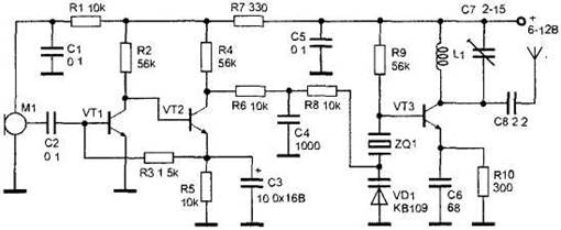
Figure 12. A radio transmitter for narrowband FM.


")
