The device (figure 11), described below, operates in a range 65-108 MHz with frequency modulation.
The range of the transmitter is about 100 m when using a compact antenna. When using the whip antenna range can reach up to 500-600 m. The signal from the electret microphone M1 type FEM-3 is fed to a two-stage low-frequency amplifier with direct connections on the transistors VT1, VT2 KT315 type. The operating point of the amplifier is set automatically by the feedback circuit to direct current through R5, R6, C3. The amplified low frequency signal from the collector of transistor VT2 through the filter of low frequencies on the elements R9, C4 and the resistor R10 is supplied to the varicap VD1 type LW109 included in the emitter circuit of the transistor VT3 type CT. The bias voltage on the varicap VD1 sets the collector voltage of transistor VT2. Single-stage RF generator is made on the VT3 transistor. The bias voltage at the base of this transistor is set by resistor R11. Transistor VT3 is connected to the circuit with a common base. In its collector circuit includes the circuit C8, C9, L1. The tuning frequency of the generator is determined by the inductance of the coil L1 and the capacitances C8, C5, VB1. Capacitor C9 sets the depth of feedback, and the capacitor C10 will agree on the loop antenna. All the details of the transmitter small. Choke DR1 type PDM 0.1 60 µh. You can replace the self-made, wound on a resistor is 0.25 a resistance greater than 100 ohms wire sew 0.1 - 100 turns. Coil L1 is frameless, with an internal diameter of 8 mm, and has 7 turns of wire sew 0.8 mm. Compact reel antenna is made the same wire, its total length is 50 cm Coil has a diameter of 3 cm. If you have a conventional antenna, the wire or pin with a length of 0.75-1.0 m. When configuring the capacitor C8 tune
the radio microphone on a free site УSW FM. Capacitors C9 and C10 are configuring the generator on the maximum communication range.
The transmitter power is about 200 mW. If such capacity is not required, it is easy to lower, increasing, however, the service life of the power source. You need to increase the resistance of the resistor R11 to 68-100 Ohm and replace the choke DR1 at a constant resistor of 180-330 0m. as in this case, the capacity of wireless microphones will be about 10 mW, the VT3 transistor can be replaced by KT315 or KT3102. Transistors VT1, VT2 can be replaced by KT3102, and the transistor VT3 - CT, CT. To power the device uses a 9 volt battery type "Crown", "Emery" or 7D battery-0.15. Due to the fact that the powerful high-frequency generators have a low frequency stability, which leads to deterioration of the interference condition in General.
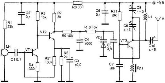
Figure 11. Powerful high-frequency radio transmitter.


")
