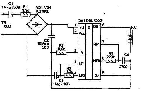
The electrical circuit of the electronic call is presented in the figure.

Permanent the supply voltage is within 11-29 In is supplied to the internal output node power with hysteresis (pin 1). Useful output current chipset - up to 35 mA at the output voltage up to 17 V, which makes it extra, amplifying the current cascade loading chip low-light and sound indicators, and also convert the output signal to control Executive devices. The load should have an impedance of not less than 150 Ohms.
The chip contains two built-in CC generator and output amplifier. One of generators connected to the terminals 3 and 4 RC-chain produces pulses with a frequency of about 10 Hz. This signal is a control for the other brand, the corresponding RC-elements of which are connected to the terminals b and 7 of the chip. The resulting amplified signal from the output of the chip (pin 8) is fed to load. The voltage to activate the low-frequency generator serves on pin 2. The inclusion of the generator depends on the value of the voltage at pin 2, therefore, it is possible to control the operation of the whole site by changing the amplitude of the voltage. So on the basis of chips DBL5001 and DBL5002 and similar can designing parametric detectors with thermal and light detectors, a guard device, a pulse generator, and other simple multifunction the instruments. And electrical parameters allow the use of these circuits in the most different devices even though they are specifically designed for telephony.
In the absence of the tone (and on-hook) DC voltage in phone line about 60 V. the Capacitor C1 does not pass a constant a stress component, therefore the conclusions 1 and 4 circuits DA1 supply the voltage is zero. Sound capsule is not active. When picking up the phone tube DC voltage on the telephone line drops to 3-6 V. When call-the call from the telephone line AC voltage (about 60 In) passes through the capacitor C1, a current limiting resistor R1, rectified by diode bridge VD1-VD4 and entered the chip DA1 - pins 1 and 4. Pin 4 is used for the internal power output of the amplifier chip, which in this case turns on simultaneously with the feeding unit. The oxide capacitor C2 smoothes the ripple voltage.
The capacity of this capacitor is chosen empirically. An increase in this the case is not recommended, because otherwise accumulated charge on the plates of C1 and low current consumption of the chip DA1 generator will work and the capsule HA1 to emit a signal CC, not only during intermittent phone calls-calls, and constantly, until subscriber receives the call. Through a current limiting resistor R2 constant voltage 10-12 In is supplied to the control input of the generator LF hesitation, and he, in turn, triggers the second oscillator, the oscillation frequency which is determined by the elements R4C4. In this case, this frequency is about 800 Hz. Sound piezoelectric capsule HA1 turns on and emits the signal CC.
The circuit uses sound primer HA1 type SMH. Instead to apply any other piezoelectric or dynamic capsule with resistance of not less than 150 Ohms. Instead of foreign chips DBL5001 and in DBL5002 the scheme without any changes, you can use the domestic circuit CRAP, AKRAP. These chips can be used to repair imported THE one in which the call is implemented on chips DBL5001 and DBL5002. All permanent the resistors in the circuit - type MLT-0,25. Oxide capacitors - type K50-29 or similar. Non-polar capacitor C4 - type CM with a group of TKE or N similar. Capacitor C1 is the type of MBM, MBGO, K73-10 or similar on working a voltage lower than 100 V.
Diodes VD1-VD4, you can use type CD or CD with any letter index.
The device in adjustment not needed. DA1 chip receives power directly from the telephone line (TL). Connect to TL is through connector, for example IS2-5. The polarity in this case is not very important.
Author: A. P. Kashkarov


