


")

Tone (frequency) set - DТМF - used in telephones, and radio stations with other devices. The article describes the receiver-decoder, which can be used in various designs. This device can be used for remote control of various devices, for transferring small amounts of information by phone or through radio stations in diagnostic status objects etc.
Bitonal DТМF signal is well defined in the presence of noise in the channel the transfer, therefore, the reliability of such remote control systems are very high. If involved all 16 codes can be quite simple to implement unidirectional telephone bridge - a device that allows you to link two the telephone line. In this case, you can call on one phone, dial the number on the second, connected to the second line. For this it is necessary to Supplement the decoder device "auto-pick" tube and to connect the outputs of the decoder with keyboard second phone via optocouplers. Four "extra" code can be used to the second control line and for "Association" lines.
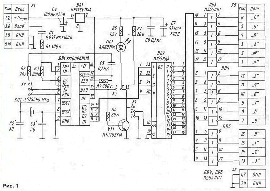
Diagram of the device shown in Fig. 1.
(click to enlarge)
DD1 chip CRUZ (import the analogs - МV8870DР, МV8870-1DР, MT, M, ACT) is a the receiver-decoder DТМF signal. The structure and operation of the chip in some detail considered in [1, 2].
In the described construction is applied typical operating circuit. According to [2] chip CRUZ is not a complete analog prototype МV8870. At last there are two versions of the table of encodings that can be selected according from the logic level on pin 5. In this design this feature is provided by a jumper x2. Chip CRUZ and have only one NM version of the table in which the tonal combination corresponding to the digit "0", gives binary combination 10102=10. When this jumper x2 must be installed in "2-W" (at pin 5 of IC DD1 - low).
Throughout most of the book [1] on p. 160 data encoded in the table. 8.7 shown with errors, as in column frequencies and in columns Q1-Q4 (output binary code). The correct option of the lookup tables DТМF and output signals binary code is given in [2] (see p. 50 ].
Chip DD2 converts the four-digit binary code output in DD1 sixteen signals that can be used to control various devices. After the receiver DD1 took bitonal parcel, the outputs Q1-Q4 occurs corresponding binary combination, which remains to the arrival of the next frame. This allows for two modes of operation decoder DD2. In the upper position of the jumper X4 ("2-3") signal corresponding output DD2 (low level) is present only during operation tone of the parcel. If you set the jumper X4 in the down position ("1-2"), the output signal DD2 will be present indefinitely until coming next tone parcel.
Led НL1 is used for display on the device and to control recognition tone of the parcel. In the jumper XS "1-2" led is lit constantly and goes out briefly for the duration of the tone. If place the jumper in position "2-W", the led will turn on only when admission bitonal parcel at the entrance DD1.
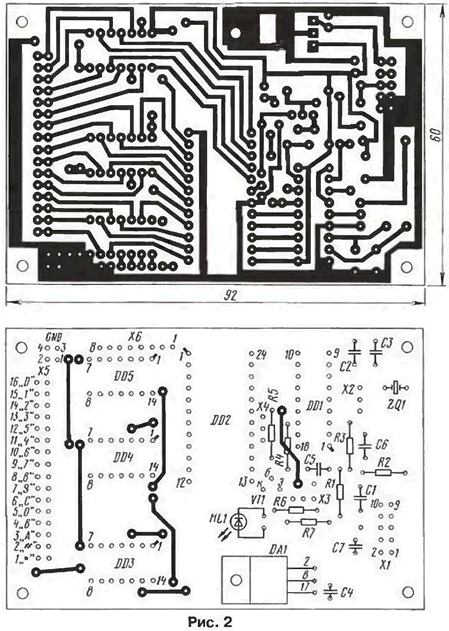
Printed circuit Board (Fig. 2) is made of one-sided glass the fiberglass. Chip DD2 can be replaced by CRIZ, but keep in mind, she had a different body.
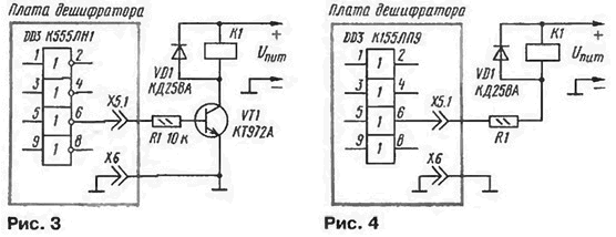
Inverters chip DD3 - DD5 used to control transistor (Fig. 3). As a buffer (without changing the printed circuit Board pattern) use a chip KLN, K155LNZ, CLP (repeater, Fig. 4). The output transistors circuits K155LNZ and CLP can work in the voltage of to 30 V and current up to 30 mA [3]. If the on-Board chip installed open collector output (RH2, VIPS,LP9). the second row of holes output connector X5 you can use it to set "pull-up" resistors.
To power the device will fit any (including unstabilized) source DC voltage at the output 8…15 V. If used chips K155 series, the current consumption is about 90…100 mA. It will be significantly less when installing the chips series KR1533, K555.
You can connect the device to the conversational node or directly to your phone the telephone line. In the latter case, the capacitor C1 must have a working a voltage lower than 160 V. assembled Correctly from the healthy parts of the device the establishment is not required.
Check the device easier to carry out, calling someone you know, installed telephone apparatus with the ability to switch mode touch tone dialing. Even better on a remote phone to use the "beeper". Made by the author, the sample is normally determined from the "beeper" which was installed at a distance of 10 cm from the microphone of the handset. Of course, this test is purely "qualitative" in nature, because it does not consider the frequency response emitter, microphone, phone line. In most cases, thus it is possible to check only 12 tones parcels("0"-"9", "#", "" ).
It should be noted that in [1] in Fig. 8.9 (p. 160) and Fig. 8.13, 8.14 (p. 162) at the switching circuit chip CRUZ inaccuracies. However, the chip works, but deteriorates the stability to the chatter and noise. Resistor R3 = 300 kω (figure 8.9) must be connected to terminal 16, and the connection point RЗ-C4 to the output 17 (incidentally, in Fig. 8.10 in this book shows the correct the connection).
Internal delay of detection of tone parcels at DТМF decoder in accordance [2] lie in the range 10…15 MS. In other words, when the respective values of C5, R4 maximum repetition frequency tonal parcels approximately is 20…50 Hz. If you consider that for one parcel is dispatched immediately four bits, for many applications it turns out to be quite satisfactory speed.
Literature
Author: O. Fedorov, Moscow