The use of such devices is justified in negotiations within a single home or neighbouring houses, because to use the radio at these distances is impractical, and the phone is now paid by the minute.
The principle of operation of these devices is based on the fact that the wires of the electrical network can transmit electromagnetic oscillations with a frequency of from 10 kHz to 100 kHz, and they can easily spread to the nearest transformer.

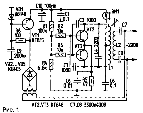
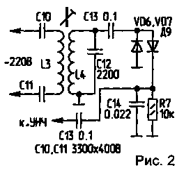
In its simplest form, this device is an RF generator (Fig.1) and detector receiver with ULF (Fig.2)
The oscillator is assembled in a conventional push-pull circuit. He is modulated in amplitude coal microphone WM included in the supply circuit of collectors VT2, VT3. Coil L1...L4 placed in cores SB-12 or similar. It is important that L1 and L4 were identical number of turns, wire diameter, and the method of winding.

L1 contains 100 loops with a branch of the middle. Wire - with a diameter of 0.1 to 0.15 mm. Both halves of the coil are wound in different sections of the frame, i.e. half in one section and half in another.
L2 contains about 50 turns of wire with a diameter of 0,1...0,15 mm and is wound on top of L1.
L4 - 100 turns; is wound similarly to L1, but without the challenge.
L3 - 50 turns, on top of L4.
To increase the range of actions can be used in the UHF receiver and power amplifier in the transmitter. For better modulation can be applied to the modulator transistors, preferably with a MIC compressor.
You should not greatly increase the power, as it leads to the appearance of interference in the equipment powered from the mains. It should also increase the frequency above 150 kHz, as it leads to the appearance of interference in the air.
Author: N. Marushkevich, Minsk; Publication: N. Bolshakov, rf.atnn.ru


