


")

It is a simple intercom will help you quickly to establish communication, useful for telephones of different premises, production areas. The communication range intercom depends on the resistance line and can reach three kilometers.
Principal its scheme is shown in the figure. Subscribers (there may 10) a telephone the devices are marked on the scheme TA1-TA. All other the elements are grouped in the remote the duty attendant (on the figure shows how it looks the remote for three subscribers) the top panel of the console are: the switch and signal lamp feed power (SA12's and HL12); switches and warning lights call subscribers (SA1-SA10 and HL1-HL10); call button (SB1); led health monitoring line (HL 11); switch sound signal (SA11); connector for connect the handset (XS1).
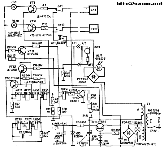
Watch how the device works in different modes.Suppose the duty you need to talk to the subscriber, the appliance is installed TA1, he translates the button SB1 in the position of the "challenge". Thus the alternating current supplied to the device TA1 chain: top the output winding of the transformer II T1, diodes VD1-VD4 and led HL11, closed contacts (on bottom scheme) button SB1, lower the contacts of the switch SA1, the device TA1, bottom outlet the winding II of the transformer, the telephone rings call and led lights HL11, signaling that the line serviceable. The subscriber, having heard the bell goes off hook, and have a conversation with the duty the human operator. In this case, the current go through the following circuit: source power the device TA1 ( handset), the lower contacts of switch SA1, normally closed contacts button SB1, microphone WM and the phone BF1 duty tube, a resistor R22, a common wire the power source. If the conversation should connect another the subscriber's call in a similar way. In the conversation can participate any number of subscribers. However, the volume slightly lower.
But if the subscriber wishes call of duty telephone operator? Then it is enough to remove up your phone of the apparatus. To the base of transistor VT1 through resistance tube apparatus, normally closed the contacts of the switch SA1 and the resistor R1 will be served a positive voltage. Transistor VT1 is opened, and will illuminate a warning light the first site HL1. Current flowing through the lamp, you will create a drop the voltage across the resistor R12, and transistor VT11 opens. On the output of the logic element 13 DD2.4 signal is 1, authorizing the work sound of the signal. The attendant will hear tonal calls will see burning lamp HL1, translate into another position the switch SA1 and lead conversation. As long beeps, sounded in the receiver of the subscriber, indicate health line, that the duty of the Central console doesn't talk to anyone.
Now let's talk about the work of the host audio signal and hooters. On the elements DD2.1-DD2.3 chip assembled DD2 a generator that generates a signal with a frequency of about 400 Hz, and on the elements of DD1.1-DD1.3 and transistors VT12, VT13 - the pulse generator with a frequency 0,3…2 Hz. If the transistor VT12 is closed, the generator generates long beeps (0.3 Hz); if this transistor is open, formed short beeps (2 Hz). At the logical element DD1.4 the signals of the two generators are summed and fed to the line telephone sets (via divider R18, R19) and using the logical element DD2.4 transistor VT14, which loaded on a dynamic head BA1.
If a call pick up the phone anyone from the subscribers, you hear the busy tone, because the transistor will be VT12 open voltage-drop created current conversational the resistor R22 (about 3 In). The duty operator too you will hear a short beep signals generated dynamic head BA1, in addition, the remote will light up signal lamp. It will connect subscriber to the conversation or ask him to hang up and to wait, and then be called as only the line becomes free. When necessary duty may to turn off the beep switch SA11.
Negotiation the device is powered from the mains. The transformer T1 network the voltage drops to 36 In (the eye is used when calling) and to the voltage of 22 V. This the voltage is rectified diode bridge VD8--VD11, ripple smoothing capacitor C5, then the voltage stabilized stabilizer transistor VT15 included in the scheme emitter follower, and the Zener VD6, VD7. The output turns constant voltage 20V. For lamps HL1-HL10 to stabilize the voltage necessarily, therefore, they feed directly from rectifier VD8 - VD11. Such the inclusion is possible to reduce the heating transistor VT15. Chip DD1.2 are powered from a simple parametric stabilizer VD5R24.
Details and design. In the device applied widely common details. In as circuits DD1, DD2, in addition to 155, you can also use a chip types 158, 555. Transistors VT1-VT10 can be any of series CTB, CT, CT, CT; VT12, VT13 - any of a series KT, KT, KT315, CT, CT, CT; VT14 - KT315, CT, CT, KT815 with any letter; VT15 - any of the series CT. KT815, CT, VT11 - CT, CT, KT361 with any letter. Led HL11 - any of series AL, AL, AL307, AL., All capacitors, in addition to C2, type K50-6 or K50-16, C2 - km-6, K10-7b, K10-17. All type resistors MLT. Switches SA1 - SA10, the switches SA11, SA12's type "tumbler" (MTD-1,TP1-2,PT, MT); button SB1 type km-1, CMD-1, KP-3, P2K, and the socket XS1 - SG-5, fork HR - SSH5. Fuse FV1 - 0,15- 0.5 A (depending on the number subscribers). As transformer power conveniently to use the output transformer personnel scan TV TCE-LM. Winding, in addition to the primary, removed and wrapped around two new. Winding II should contain 410 turns of wire sew-2 0.12 mm, winding III - 250 turns sew-2 0,25 When disassembling mm. the transformer should be careful, otherwise you can cut the findings the primary winding. Transistor VT15 installed on dural plate dimensions h mm - it serves the radiator. As dynamic heads BA1 or BF1 the used primer TA-4 the resistance of 65 Ohms. Coal the microphone WM - any type for example, MK-16-W.
Phone the apparatus may be, for example, TAI-66, TAN-70. If you use the device with faulty dialer, disable from him conductors and connect them to lever the switch so that when lowered the tube to the line was connected call through capacitor 1 µf, and when raised - consistently United microphone and phone.
When verifying and establishing intercom the selection of resistor R23 set the desired tone the audio signal. Resistor R22 pick such that when the flow of the current conversational through him and the machine falling voltage was not less than 3 V.
For connection telephone devices with remote standby the human operator can use any wire.
Author: A. Evseev; Publication: www.cxem.net