


")

If the apartment has several telephone sets (TA) in different rooms connected to one telephone line, this unit you just need. When a call is often off-hook all THE same, which causes complications in the beginning of the conversation. If you want to call from one room and the other at this time, is a phone conversation, we have repeatedly pick up the phone to learn freed the line. There are also the cases when one of the telephone sets is bad on the phone and not knowing about it, you don't need to wait for a call.
Get rid of all these inconveniences will help electrical diagram in Fig. 2.1. It allows you to have light indication when removing the tube on any of THAT.
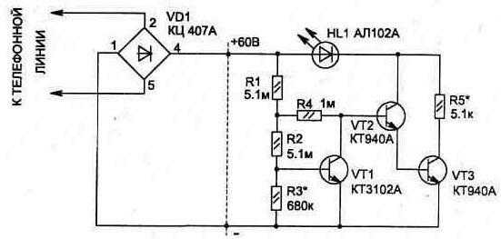
Fig. 2.1
The scheme is connected to the telephone line in parallel with THAT in any convenient place, for example, you can install it inside the case of each TA, securing HL1 led in a visible place.
Electric circuit can be simplified by eliminating the diode the bridge VD1, but to connect the device to a telephone line requires observing the polarity shown in the diagram.
The operation of the device is based on the use of changing the voltage on the telephone line. So, if the telephone line is not busy, the voltage on it about 60 volts, and when hook on any of THAT, it reduced to 6…15 V (depending on internal resistance).
The scheme consists of a level detector voltage line transistor VT1 and current amplifier to VT2, VT3. Transistor VT1 operates in microcurrents that provides it maximum gain. For this the reason he will be in one of two States: locked or open, depending on the supply voltage.
When setting the voltage indicator will require selection of the resistor R3, and in the manufacture of a valid schema apply R1, R2 - 3 MW 5.1 MW and R4 - 750 kOhm to 1 MOhm.
HL1 led can be replaced or any ALA from the TRC, and VD1 diode bridge of four diodes type KDA, B.
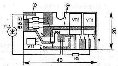
Fig. 2.2. A printed circuit Board,
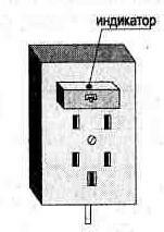
Fig. 2.3
Verification of circuit operation is best done by filing from regulated DC voltage 6…15 V (it should glow the indicator HL1). Gradually increasing the voltage up to 30 V, you should make sure that at a voltage of more than 20 In the led goes out.
The scheme proved to be reliable in the work and has no effect on the telephone line.
The current consumption of the circuit from the telephone line when lowered the tube does not exceed 0.01 mA.
Topology sided PCBs and the elements in it (without VD1) is shown in Fig. 2.2. Board size selected with the possibility to install it in a standard telephone socket (Fig. 2.3).
Publication: www.cxem.net