


")

Modern PBX systems have found wide application in organizations and the institutions. They allow you to extend the capabilities of the telephone when a limited number of lines. Typically, the main element of such stations, the processor or microcontroller. The author proposes to use instead personal computer, fortunately there are now a large number of computer technology, which is a bit outdated, but it can not perform such a very the complex task of managing a PBX.
Developed PBX is a software - and hardware-based IBM PC. The unit is connected to the LPT port of the computer, equipped with a sound card, uninterruptible power source and the operating system (OS) Windows95/98 or Windows NT4.0/2000/XP (the latter is preferable for reasons of reliability). Of course, the computer must be running constantly.
Telephone equipment connected to a PABX, you may be quite varied: a single disk or a touch-tone telephone with DTMF or pulse dialing, cordless telephones (cordless phones), modems, Fax machines, etc. The total number of internal and external lines 14, the maximum number simultaneous connections - 5. In the PBX provides the most possible galvanic isolation: galvanically connected only those kits that are currently in the mix.
Basic functionality:
- flexible incoming call distribution and selection of external lines;
- callback when releasing the line was busy;
- transmission connection to another subscriber, call pickup;
- day/night mode - ability to change system settings in based on the current time;
- e-the recording of the caller - the possibility of consultations with the second subscriber, giving the first end;
- musical pause in hold mode (playback MIDI file);
- autodial (when you pick up the handset automatically connects to the external line);
- alert - if the extension is in the connection state with the external line and receives an outside call on the other line, he hears two short the tone;
- system operational report - the system continuously analyzes the workload resources and gives a full report on all the connections in a text file;
- the transformation tone dialing in pulse.
ATS consists of several modules. The basic module shown in Fig. 1. He contains interface circuits DD1 - DD9 for connection to a computer, the source power subscriber unit (hereinafter AK) and the connectors HR, X1- × 17. Power source AK includes a generator for the elements of the chip DD10, transistor VT1 and the transformer T1.
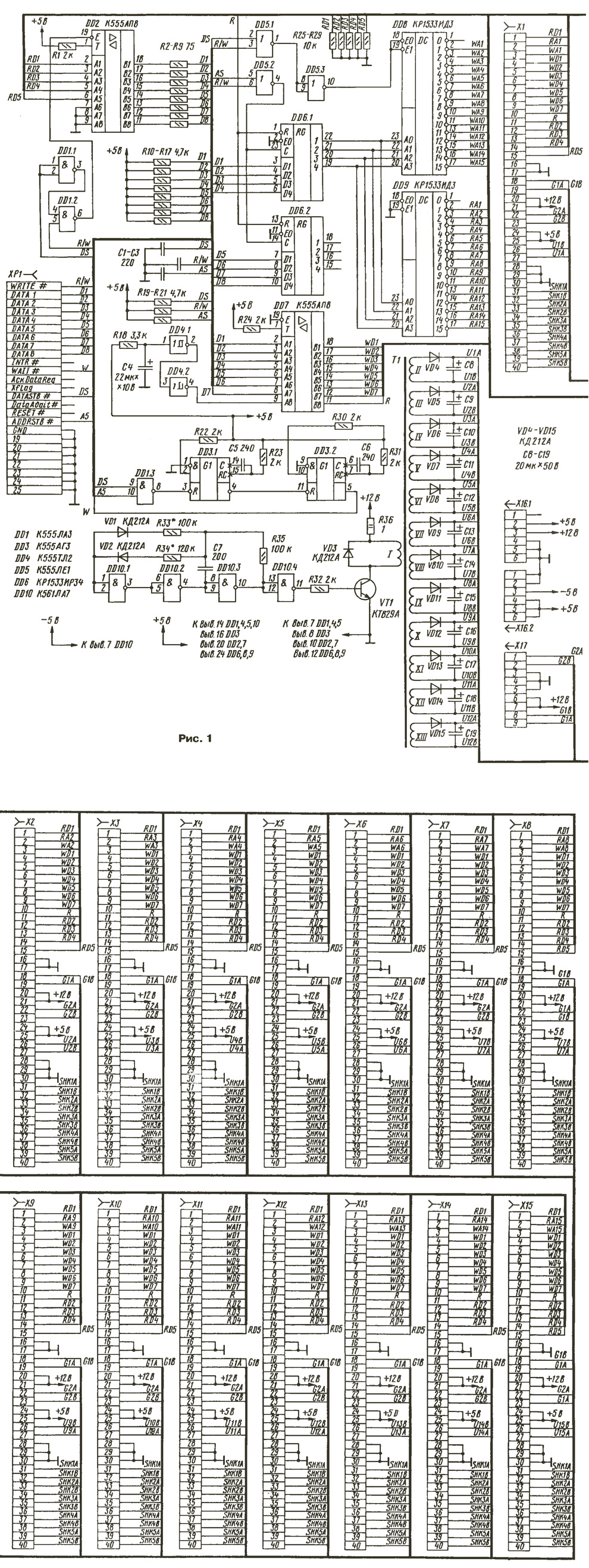
(click to enlarge)
Connector HR is designed to connect the PBX to the LPT port of the computer, × 17 - to unit generators (see below). CH-X15 can connect AK, sets external lines (SWЛ) and music kit (MK). Same contacts 1, 4-25, 28-40 connectors X1-X15 are interconnected; 2 and 3 are connected to the proper the outputs of the decoders DD9, DD8; 26 and 27 to the respective rectifiers for power +36 In AK. For SWЛ and MK such tension is not necessary, therefore, to connectors X13-X15 it is not served, and the transformer T1 includes a 12 and not 15 the secondary winding. Connectors X13-X15 are designed to connect only SWЛ and MK, and X1 - XI2 - for all sets. The appropriate device type must be installed in the program CTIServer.exe (to do this, double-click the left click in the column "Type" in the corresponding row).
The X16 connector connected to a standard power source from IBM PC AT May the use of any other source with an output voltage of +5 V and +12 V at a current 2 A and -5 V at a current of 0.25 A.
To power the AK assembled transducer has a frequency of about 20 kHz on the elements chip DD10. If necessary, the frequency and duty cycle can pick up resistors R33 and R34. For more reliable closing of the transistor VT1 on the pin. 7 DD10 voltage is -5 V. For each AK provides its own the secondary winding of the transformer T1 and the rectifier. This version of the power AK provides isolation to unleash all AK and not use adapter transformers in SWЛ (as is done in [1]). The use of transient transformers degrades the quality of the speech signal and adversely affects the speed of data exchange via modem.
The transformer T1 is made on the ring size CHH ferrite M2000, the primary winding has 24 round of PEV-2 0,5 - secondary coil 72 the PEV-2 is 0.2. Transistor VT1 is mounted on the heat sink area of 30 cm2.
VOSL of each connector and the chip, it is desirable to connect the locking the capacitors in the power supply (not shown).
As connectors X1-X15 can be applied MPN or ISA, taken from the faulty motherboards of computers.
The interface consists of input buffers DD2, DD7, register-latch address DD6, the signal generator WAIT DD3, the address decoder of the data read mode, DD9, the address decoder of the data recording mode DD8. Buffer DD2 in the data read mode, is in normal condition, the rest in vysokoimpedansnye.
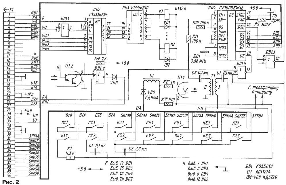
A schematic diagram of a subscriber's set (AK) is shown in Fig. 2. He is from the current limiter L1R2R3U1.1 (25 mA), receiver tone dialing DD4, register-latch data DD2 to the decoder DD3 and the switching field K1- K7.
(click to enlarge)
Relay K1 is used to supply ringing voltage, K2 - signal station, K3, etc. - to connect to a cord sets (SCH). Under HQ is understood to be the a couple wires that you can connect to talk. The number of relays for connect to HQ all sets must be identical and must be equal to the maximum number of simultaneous connections is regulated in the window settings\parameters. It is chosen based on the number of internal and external subscribers lines.
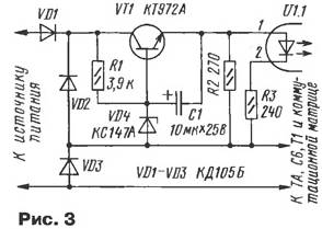
The subscriber's set design can be improved by applying instead of the limiter the current stabilizer transistor (Fig. 3), and simplify (somehow worsened the recognition quality tone dialing). To do this to exclude the transformer T1 and the elements R7, R11, to replace the chip on DD1 CLE, and pin 2 IC DD4 be connected to pin 5 of the new chips DD1 through a capacitor C6. In this case, the signal will pass through the optocoupler. Receiver tone dialing is generally not required if the city or PBX the phone does not support this type of dialing.
Instead of the inductor L1 and the optocoupler U1 perhaps the use of electromagnetic relays, for example RES9 (passport 205). Cons of this option: contact bounce and uncertain responses on long subscriber lines with great resistance and different phones.
Receiver tone dialing DTMF assembled on a chip CRUZ, described in detail in [4, 5].
As the inductor L1 is applied to the winding of the magnetic circuit from the relay RES (passport 205). Winding different AK to be shielded from one another or post in space, as otherwise may be monitored conversation with neighboring SCH. The transformer T1 is made on an armored magnetic circuit B18 x 3 x 10 ferrite M2000 and contains two windings 300 turns of wire sew - 2 to 0.1.
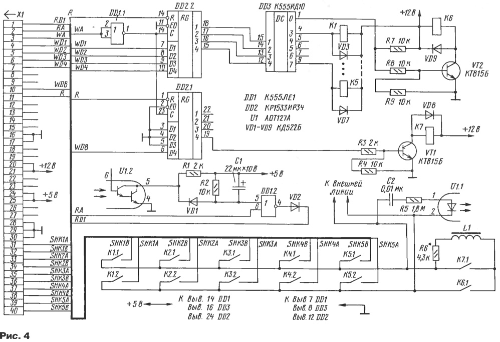
Diagram of the set of external lines is depicted in Fig. 4. Unlike the AK, there is no receiver tone dialing, there is no relay for the filing of the ringing voltage and the signal station, but there is a receiver of the incoming call.
(click to enlarge)
As in AK, relays K1 - K5 are used to connect to HQ. This number is expected to be equal to the maximum number of simultaneous connections and windings must be connected to the outputs of the decoder, starting with 3.
When connecting the external lines to the PBX it is desirable to consider the polarity to avoid loud clicks in handsets due to the recharge of the separation the capacitors.
As the inductor L1 is also applied to the winding of relay RES (passport 205). When need the current in the external lines can pick up resistor R6.
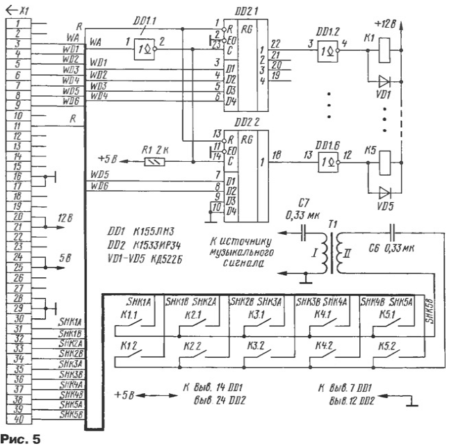
The scheme of the music set is shown in Fig. 5. It consists of dividing transformer T1, the register - latch data DD2 without decoder that allows to enable sound filling more than one HQ and the switching matrix. Music filling is an important component of the ATS, as people who call the office, which features this PBX as a rule, does not wait until one the extension will consult with others. If the caller at this point hears silence, then hangs up because it is difficult to understand what happened - or disconnection for technical reasons, or outside line is in the mode the deduction.
(click to enlarge)
The source signal may be different: sound card, CD-ROM, FM tuner or external. Software CD player or media player should be included with the circular playback of one or more files.
If the source signal contains a power amplifier, it must to collect, for example, on a chip CAN and turn in front of the transformer T1.
The transformer T1 is made on an armored magnetic circuit B18 x 3 x 10 ferrite M2000 and contains two windings 300 turns of wire sew-2 to 0.1.
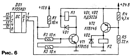
All the kits used relay RES with an operating voltage of 12 V, but they can to be any appropriate voltage, and transistor (more cumbersome). When using keys it is possible to apply less dear decoders CID (Fig. 6). When connecting relays transistors have be guided by the parameters of the chip KID: current - not more than 80 mA, the voltage does not exceed 15 In [6]. You can use optorele P [7, 8] (more expensive option).
The block diagram of the generators shown in Fig. 7. It consists of a source of the call the voltage generator and the signal station. RC-harmonic oscillator frequency 425 Hz built on a bridge Fault [9]. The assembled chip DA1 specifies the node on the transistor VT1 - voltage, VT2 - emitter the repeater.
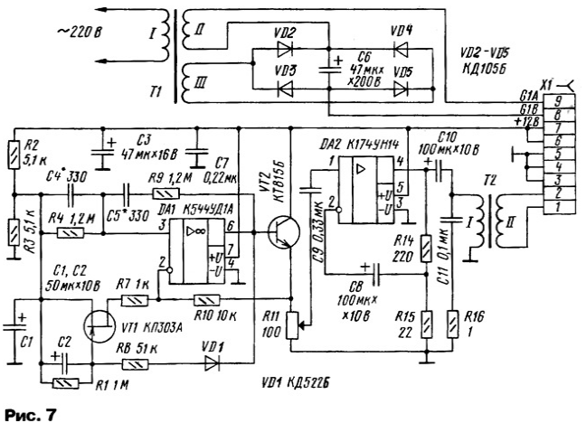
The output impedance of the generator should be as small as possible to exclude getting the signal tone dialing from one to another at AK simultaneous connection to the generator. This applied to the amplifier chip DA2 and the transformer T2. The driver of the ringing voltage is made on a network transformer T1 with a rectifier diode VD4-VD7. It creates an alternating voltage of 60 side 50 Hz with a DC component.
As applied standard T1 transformer TAN 13-220-50K. It contains four windings 30 side. Winding II consists of two series-connected windings 30, similarly to the winding III is composed of two windings on 30 V. You can use another transformer with two secondary windings 60 Side.The transformer T2 is fabricated on a ferrite shell-magnetic core Bhh ferrite M2000 and contains two windings 50 turns of wire sew-2 to 0.5.
The proposed variant of the location of the PBX nodes, where each set is assembled on a separate Board with a connector, not the best, but for the understanding of the work station. The author has collected ATS on development boards, three blocks, placed in the standard case of the IBM PC:
- all relays and manage decoders;
- a voltage Converter with rectifiers for power AK;
- all other elements.
The best option where collected on the same Board two or four sets (in depending on the dimensions of the relay). In this case you have to use connectors with a large the number of contacts.
We now turn to the description of the software.
Installation. Unpack the archive ats_pc.zip on drive C. In the directory C:\ATS\MIDI must be the music file.mid, which is when the program starts CTIServer.exe will start playing in a circle. Start reg.bat. If the computer operating system (OS) Windows95/98/ME, just connect PBX to the parallel port on the PC (when the computer is powered off and ATS) and run CTIServer.exe. Pre-need to check the mode LPT port: it needs to be ERR.7 or ERR.9.
Windows NT4/2000/XP imposes a ban on direct appeal to the ports. It can to bypass driver PORTTALK.SYS. For this you need to download the archive porttalk22.zip with [3], unzip it, copy porttalk.sys in the catalog C:\WINNT\SYS-TEM32\DRIVERS (for Windows XP - C:\WINDOWS\SYSTEM32\DRIVERS); to copy Allowlo.exe in directory C:\ATS; run instead CTIServer.exe need ats_winnt.bat. Under OS Windows 2000 PBX worked for several months without interruption.
Properly collected PBX in adjustment is not needed, although when connecting long subscriber lines have to pick up the resistors R2, R3 (see Fig. 2) current in line 25 mA without the receiver of the telephone. Optocoupler should confidently be triggered.
Briefly about the logic of the exchanges. Extension 1 picks up the phone, through the 0.2 seconds it you hear the signal station. After that, he can dial the two-digit number. If this number corresponds to a certain extension, such as 2, in the SLEEP state, the user 2 is assigned the status RINGJNT, and subscriber 1 - RC (RING CONTROL). In this case, the subscriber 1 hears the control of the parcel call (long beeps), and the subscriber's telephone set 2 receives the call signal. If a subscriber 2 will pick up the phone, it will connect for free SCH. If the subscriber 2 is busy, there is no free HQ or the dialed number does not match internal subscriber, the subscriber 1 hears the busy tone (BUSY condition).
All of the current state of the kits can be observed on the monitor screen in the main window CTIServer.exe and read in the log files, where they are fixed with time-stamped.
When you receive an outside call, the status assigned to the internal RINGJEXT subscribers on the list, editable in the properties of the trunk. To to get to the properties window for a device, double-click the left click in the column "Type" in the appropriate row. For day and night modes of operation of the station there are separate lists.
If the extension dialed digit 9, is connected with the first free external line from the list stored in the properties window of the subscriber (also for day and night modes of the lists). In this window you can prevent the outside of hotel, set alarm mode and unconditional external classes line. You can select a specific outside line by dialing the digit 8 and the sequence number line in the list. For example, 82 corresponds to the second line of the list.
If the subscriber properties included "occupation", then as soon as he picked it up, will be connected to an outside line (ie, no need to dial 9). In this if he wants to call another extension, room before he have to dial the * key (i.e. not, for example, 12 *12). When the priority class is the connection to an external line even in the event that if it is busy (previous connection is broken). Dialing another an extension is also available through the *button.
The signal tone dialing takes place in an external line through the separation capacitors freely, so any additional measures not to take necessary. Pulse dialing so will not work. From the separation capacitors can not refuse, therefore, this function implements the program. If the extension is in a call with outside line and there is a gap it loop for a time greater than timeO, and less than timel, this is regarded as pulse dialing. This impulse is transmitted in external line by means of a rupture of its loop at a time that is set using variable pulseouttime in the configure\parameters.
The program also provides the transformation tone dialing in pulse. This is necessary when a handset is included in the DTMF mode rooms, and urban ATS this mode is not supported.
If the extension 1 is in a state of connection with an external line or with another extension 2 and there is a gap it loop for a time more than timel, and less than time2, it is regarded as an output in the SERVICE mode, that is confirmed by two short beeps. The connection of subscribers 1 and 2 torn, the subscriber 2 begins to hear the music. Thereafter, the subscriber may 1 to dial any extension (for example, 3). If the subscriber 3 pick up the phone connection is established between subscriber 1 and 3, the subscriber 2 in this he continues to listen to the music. If the subscriber 1 and subscriber 3 hang up on more than time2, will connect subscribers 2 and 3 or 2 and 1 respectively. Can not wait for the other person hang up: if a subscriber 2 or 3 will produce rupture of his train on time more than time1, and the least than time2, we will connect subscribers respectively 2 and 1, or 2 and 3.
In the configure\parameters can also adjust the duration of the period time, after which it is believed that pulse dialing digits is finished (mezhtsifrovaya pause), duration of call, its control and pauses between them (RING / RING CONTROL), the short duration of the tone (BUSY). Here you set the time automatic switching from day to night and Vice versa.
If an extension user tried to connect to an outside line, but it was busy, he will hear a short beep. If he dialed the number 6, will turn on mode WAIT, what is confirmed with two short beeps, then he puts the handset. Once the external line becomes free, he will receive the call. For several subscribers with the mode of WAIT queues.
The system allows also the mode of "call pickup". If the subscriber 1 received a call from the subscriber 2 or an outside line, but he didn't answer it, the caller 3 by typing at its telephone number 4 and the personal number 1 sets the connection with subscriber 2.
Translated from day to night and Vice versa, is done automatically by set time or manually from any phone. To do this to gain 782# or 781#, respectively.
Analysis of the market of personal computers and office PBX showed that sold models PBX (Panasonic, LG, etc.) when the same number extensions and external lines have a price in excess of cost described PBX is more than 5 times (excluding the cost of the IBM PC). Low requirements software PBX to computer resources allow use inexpensive models (enough R, 32 MB RAM, 540 MB HDD). You can connect a PBX to a dedicated server.
Software for PBX and additional information on the use of port SWU.
When connecting device to the telephone network of General use, you must obtain a certificate.
Literature
Author: Sergei Kunitsyn, Kaliningrad