Most viewers would like to get rid of obtrusive ads transmitted during the transmission on almost all channels. The author published here the article suggests applying device, which optionally allows the viewer to reduce its volume for a while, and then automatically restore normal reception of the program.
Periodic watching television has become an integral part of life the majority of people. But because television now can not exist without advertising technology, all viewers, to a greater or lesser extent, become their consumers. The avalanche of advertising, following one after another during the most interesting programs, most often cause irritation, but can break mental balance, which affects the microclimate in the family and at work.
Usually viewers who do not wish to listen to the ads, lower the volume or completely turn it off the buttons on the remote control or the front panel of the TV. However, after the advertising re-adjust to the desired volume, not only uncomfortable, but usually slowly, or in time to include the missing the sound, which is very often forgotten, if the viewer was briefly distracted. And some viewers switch the TV to other programs during commercials and returning to the original channel, often already after conceding part for transmission.
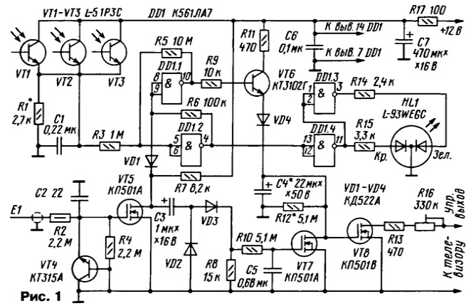
To reduce irritation, prevent unwanted effects from advertising and to reduce such inconvenience can, if we apply the proposed device. Its schematic diagram is shown in Fig. 1. It allows for a little while (a few minutes) to mute the TV. Device control or laser pointer, or touch sensor. The design can be built into any TV with an analogue electronic volume control, and with a slight revision of the device and the TV is in any other.

At power up, the device does not manifest itself, and sound support is at the desired volume. If at least one of phototransistors device to cover short-term beam laser pointer (a then to turn it off), the sound volume will decrease on the time set in the device (from the author about 3 min). After this time the volume automatically returns to the original. If there are laser pointers, the same the thing you do, briefly touching the sensor. When using a sensor becomes possible and off a lower volume if advertising ended before the set exposure time
Consider the case of a control laser pointer. In the initial state, when no one of the transistors VT1-VT3 is not illuminated, the total resistance is large, the voltage across the resistor R1 is close to zero, which indicates that the level On the inputs element DD1.2. At its output and, consequently, the inputs of the element DD1.1 to be level 1, and the output of this element is level 0. The emitter follower at the transistor VT6 is closed, the capacitor C4, which determines the exposure time, discharged. The voltage at the gate of a field effect transistor VT8 is zero, and it is not affects the sound level. Double-crystal HL1 led is lit in green, indicating the device is ready to work.
If even for a short time on one or more of the phototransistors will be hit by the beam laser, the voltage across the resistor R1 will be more than half of the supply voltage chip DD1 and all its conclusions, the information voltage level are inverted. Moreover, it should be remembered that the condition persists until long as at least one of the phototransistors lit. HL1 led is lit in red, indicating a passing team. Emitter the follower transistor VT6 is opened and the capacitor C4 is quickly charged voltage 10...11 V. the voltage at the gate of the transistor VT8 is becoming a lot more than its threshold voltage to open, it opens, connecting series-connected shunt resistors R13, R16 to the control circuit volume level, and it goes down.
After removal of the beam pointer with phototransistors or shutdown items chip DDI and the transistor VT6 is returned to its original state. Capacitor C4 begins to discharge through resistor R12. When the voltage across it will be close to the threshold voltage of opening of the transistor VT8, volume will rise to a previously set value. Smooth restore volume depends on the drain current of the transistor VT8. Diode VD4 prevents discharge of the capacitor C4 through the emitter junction of transistor VT6. The inclusion of elements DD1.1, DD1.2 according to the scheme of the Schmitt trigger allows you to get the level of charging of capacitor C4 is more stable.
If you use a laser pointer uncomfortable, to control the device sensor E1. When you touch your finger to it on the gate of the transistor VT5 induced alternating voltage. The transistor VT4, working as a Micropower the Zener diode protects the transistor VT5 from breakdown paddle. The transistor VT5 works amplifier current and voltage. With a short touch (split second) to the sensor inputs on the element DD1.1 receives multiple pulses of level 0. At all information pins DD1 levels are inverted, the transistor VT6 is opened and the capacitor C4 is quickly charged. Then everything is the same. as when controlling a laser pointer.
The sensor also allows you to turn off a lower volume if, for example, advertising ran out before the set time delay. For this purpose the finger at the sensor holds more than one second During this time, the capacitor C5 will have time charged up to voltage 2...4 V. the transistor VT7 will open and drain the capacitor C4. The transistor VT8 is closed, the volume will increase. Resistor R11 limits the inrush current through the transistor VT6 is open when the transistor VT7.
Control output devices are connected to the active input of the block or node electronic volume control. In TVs ZUSTST-USCT with blocks radio SMRK-1-5, SMRC-2 output is connected to the output 2 of these units (i.e. conclusion 8 block UPCS-2 or pin 7 UMCS-sh-1, or pin 5 of the chip CUR or TBA120U). If your TV is set to a submodule of the Ombudsman of sound MIND or 1-2 similar dual-system module M1-6-1, the unit is connected to the output
7 this block (i.e. to the pin 5 of the chip CUR, CUR or TBA120S). If the TV contains the module channel SMRC-41-2, the output is connected to its output 13. If the tract sound processing built on a chip CRHA or TDA3827, her the entrance control volume o 16 (TVs "Horizon - CTV-601" and etc.).
The ability to install devices in modern domestic and imported TVs with monachesi determined after analysis of the concept of subject the finalization of the apparatus and the assessment of their own capabilities.
8 some cases to connect the design to use low-power electromagnetic relay, which at the time would include dynamic head of TV via a series resistor. To implement such an option control transistor VT8 should be more powerful.
In the device, you can use resistors S1-4, S2-23 S2-33 and other similar; trimpot R16 is any compact. Oxide capacitors - any remaining - K10-17, km-5, km-6, K73-17, K73-24. Capacitor C4 should to be smaller leakage current. Indicated in the diagram, the diodes are replaced by any of the series CD, CD, KD521, 1N4148.
Transistor KTA (VT4) - any of the series. Suitable Zener diode, for example, CSA (cathode to gate VT5, anode to ground). Field transistors - any of the series K. ZWN2120, ZN2120 and the like. The transistor VT6 you need to set a smaller initial current collector, otherwise you will need to reduce the resistance of the resistor R12, the proportional increase the capacity of the capacitor C4. Will fit any of the series CTS, CT, CT, US, VS, SS9014, 2SC1222, 2SC1845. Chip CLA interchangeable analogues CRL, CD4011A
Phototransistors L-51P3C Kingbright company have the dark current not more than 100. Their replace similar L-51P3. Instead, you can apply and domestic IR photodiodes, for example, FD, FD Phototransistors, etc. on the front panel the TV set in the corners of a triangle, and led HL1 placed in the center, which will greatly facilitate the mouse laser pointer. The led can be any similar double-crystal, for example, L-93WGYC.
The current consumed by the device, does not exceed 35 mA.
The TV can be connected to any secondary source stabilized voltage 9... 12 V, not galvanically connected with the mains voltage. In the old Soviet television, as a rule, there is always sufficiently powerful source voltage of + 12 V to the +9, +12 V.
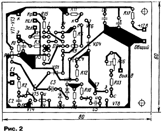
Parts of the device are mounted on one-sided foil-clad circuit Board, a drawing of which is shown in Fig. 2. Desirable shielding her.

Establishing device is reduced to the selection of the resistor R1 so that the sensitivity of the phototransistors were insufficient to enable false the device at the bright light of the room. If the phototransistors to replace photodiodes, the resistor R1 may have a resistance of several tens and even hundreds of the shortfall. The time delay, which would decrease the volume, depends from the values of capacitor C4 and resistor R12. Podster-brush attachment resistor R16 set the level lower the volume. The sensor, which can to use, for example, a miniature metal body of the transistor, connect to the device with shielded wire.
Author: A. Butov, S. CORBA Yaroslavl region


