For several years in our city is being encoded broadcast on 29th channel. To implement sufficient protection against unauthorized viewing of programs used multivariate address coding system, developed in Russia and used by many commercial television studios. Visually I of the program is not coded lowercase and frame synchronization.
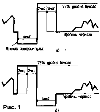
When viewing the full television signal using the oscilloscope was able to detect that the coded signal is absent HR clock, and instead of lowercase pulses are synchronization pulses, shown in Fig.1. The number of lines over which signals are transmitted as shown in Fig.1 and 16, changing periodically, and it is one of the coding options. There are also changes to the pulse duration of the high level (75% white level), depicted in Fig.1. The address of the subscriber and information about the encoding is transmitted during 1 μs at the end of each line.
However, you can make descrambler, is able to convert encrypted program in a standard full color television signal (PTSTS) when used on the transmitting side of any of the built-in method encode.

To make such descrambler using the fact that the position of the transition pulses with low level (the level below black) on the pulse of the high level (Fig.1) is constant in time and coincides with the beginning of vertical sync. Human clock can be obtained, taking account of the number of rows that are sent.
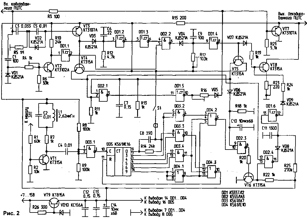
Schematic diagram of descrambler that implements the described principle and provides automatic recognition of coded programs, depicted in Fig.2.

(click to enlarge)
On the VT3 transistor assembled the selector pulses of low level, which, after separation and inversion charge the capacitor C6 and to the input of Schmitt trigger DD1.2. The time constant circuit R12, C6 is chosen so as to increase the duration of these pulses is 1...2 ISS. After inverting the element DD1.3 these pulses come to one of inputs of the element DD2.2. Pulses of high level are distinguished by the transistor VT2 and, after inverting the element DD1.1, serves to the second input of the element DD2.2. Thus, in the presence of the coded signal shown in Fig.1, the output of the element DD2.2 are formed the horizontal sync pulses. Using elements VD4, R17, C9, their duration is brought up to standard (4,7 ISS), and after inverting the element DD1.4 they come to the base of transistor VT8, which, opening, "vreset" in their PTSTS. Resistor R23 is used to adjust the level of these pulses.
To ensure the suppression of false sync pulses (Fig.1 (a) are the elements VT4,VT5, DD2.1, DD1.5, VD5, R16. After the selection transistor VT3 all the low level pulses are received at the emitter follower VT4, and then to one of inputs of the element DD2.1. To the other input DD2.1 receives the signal generated by the element DD1.4 (pasted flyback pulses). Chain VT5, R13, C7 serves to increase the duration of these pulses is up to 70... 110 μs. Consequently, the output of the element DD2.1 in the case of signal reception, depicted in Fig.1 and, after passing the first encoded strings pulses appear. It pulses, exactly corresponding in duration and location of the false fronts of the pulses that are present in the coded signal. The element DD1.5 inverts them, and through the diode VD5 with series resistor R16, which is used to adjust the degree of suppression of the false sync signal is supplied to the base of emitter follower VT7.
Frame-synchronization is carried out by counting the number of rows. It is convenient to use the voltage of the filament of the picture tube (CRT). Almost all modern TVs the filament voltage for the tube is supplied with the transformer horizontal and contains higher harmonic components, which are necessary for the operation of descrambler. On the VT1 transistor and the resonant circuit L1, C2 is released the second harmonic of the line frequency. After inverting the element DD3.1 twice the horizontal frequency comes to the counting input of the chip DD5.
Elements DD3.2, DD3.3, DD3.4, DD4 are used for forming the frame synchronization pulses which appear at the output of the element DD4.2, and reset the counter DD5. Button S1 is designed to adjust the phase of the frame synchronization pulses.
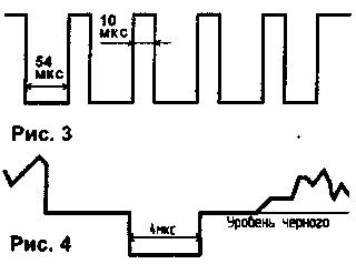
Thus, on one of the inputs of the element DD2.3 come impulses framerate 288 duration ISS (4,5 lines). The other input of the element DD2.3 is connected to the capacitor C10, which in the case of reception of the coded signal charges of the horizontal sync pulses. Upon the reception of regular TV broadcasting, the voltage at the input 9 of the element DD2.3 corresponds to a logical zero, and descrambler automatically terminated. When you receive encoded programs, inverting transistor VT6, the frame synchronization pulses are input to the element DD2.4, which in conjunction with elements VD8, R25, R11 and DD1.6 performs the function of their "cutting" (Fig.3). "Cutting" human clock is necessary to ensure horizontal sync during the passage of the human clock. After that staff clock in the same way that both uppercase "bumps" in PTSTS.

The appearance of the decoded signal is shown in Fig.4. Transistor VT9 assembled stabilizer voltage.
Design and details
All resistors used in descrambler, adapted to the capacity of 0.125 watts. The exception is R26, which should provide a power dissipation of 0.5 watts. The permissible deviations of the values of the elements: C2, C6, CN, R12, R25 - ±5%, others ±20%. The inductance L1 is wound on a toroidal magnetic core of ferrite brand MNN with dimensions HH mm and contains 110 turns of wire sew 0,1. To the quality factor of the coil L1 does not impose strict requirements, so it can be wound on any other magnetic core. All transistors and diodes can be any alphabetic codes. Instead DD1 can be used CTL: instead of DD2 - CLS, 155, CLS, CLS; instead DD3 - CLA, CLA; instead DD4 - CLE, CLE. Capacitors C12, C13 should be placed in the vicinity of circuits DD1, DD2.
The connection to the TV
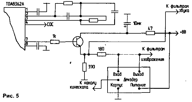
The described descrambler you can connect to virtually any TV (except tube), it is necessary to include it in the open circuit low frequency video signal with amplitude 2...4.5 V. In TVs ZUSTST, USCT, USCT of descrambler is included at the output of the module channel. In television sets manufactured in the West and in USCT of descrambler activated after the emitter repeater, which is located between the video processor and ceramic bandpass and rejec-Torno filters. An example of connecting to a TV with video processor TDA8362A shown in Fig.5. The dashed line in the figure shows the chain must be terminated.

Adjustment
To install the engine of the resistor R4 to the left in the diagram position. Turn on the TV on the encoded program. Be set using a resistor R17 pulse duration at the output of the element DD2.4 is equal to 4...of 4.7 µs. Connect an oscilloscope to the output of descrambler and move the slider to the resistor R23, to achieve equality of the amplitudes of the transmitted and the time the horizontal sync pulses. Then using a resistor R16 to set this value to suppress false sync pulses, the signal present at the output of descrambler must correspond to Fig.4. In the last turn by the rotation of the engine resistor R4 to achieve the best reception quality of the decoded program.
Describes descrambler was successfully installed in TVs, Philips, Samsung and Electron TZ". All this modified TVs took scrambled channel with almost the same quality as non-coded. After equipping this descrambler TV, you receive the opportunity to record encoded programmes on the VCR. It's enough to connect the WOOFER output on the TV with ICH-input of the VCR and turn on the last record.
Literature
Author: V. Meshcheryakov, Tambov; Publication: N. Bolshakov, rf.atnn.ru


