Described tract image is specially designed for miniature TVs. It is built on a direct amplification and allows you to receive signals in one of the first five television channels. Schematic diagram of the circuit for the first channel shown in Fig.1. Sensitivity it is no worse than 250 µv. The selectivity for the upper adjacent channel is the same as in standard TVs. Clarity vertical wedge table TIT 0249-300 lines, due to poor focusing of the beam in the picture tube of small dimensions. Power consumption does not exceed 200 mW.

Fig.1
The tract consists of the RF amplifier (T1 and T2). video detector (D1) and amplifier (TK-T5).
High-frequency signal from the antenna is routed directly to the RF amplifier. In the first stage using the capacitor C2 is a partial neutralization of the passing capacity of the transistor T1, which significantly improves its performance. The selectivity of the amplifier circuits is provided L1C4 and L3C8, tuned to the carrier frequency of the image. A feature of the amplifier is. what bandwidth it (about 2 MHz) is much smaller than the width of the spectrum image signals (6.5 MHz). Moreover, since after the amplifier the signal goes directly to the video detector D1, the result of a narrow band of frequencies occurs error detection. The suppression of the lateral components of the television spectrum in the RF amplifier is compensated by the rise of amplification at these frequencies in the amplifier.
The transistors T3 - T5 amplifier are connected directly. The entire amplifier covered by the negative feedback through the resistor R9, which simultaneously stabilizes and mode of operation of transistors T3-T5. In addition, each of the stages of the amplifier are covered by negative feedback through a resistor in the emitter circuit.
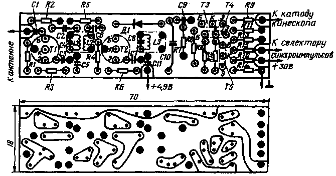
Structurally, the path executed on the Board of fiberglass, foil on both sides (see Fig.2) Foil side parts performs the functions of the screen and when inserting the foil in several places soldered to the chassis. On the Board installed capacitors CD-16 (C4, C8, C9), K52-1 or K53 (C10) and km (the rest), resistors MT-0,05 (R9) and MLT-0.125 or KIM-0,05 (rest). Coils L1 and L3 are wound on frames with a diameter of 5 mm and contain 6 turns of wire PEL 0,62. The coil L2 is wound on top of L1 and contains 3 coils wire PEL 0,31. The winding of all coils-ordinary. Tweak carbonyl M4 cores.

Fig.2
When establishing the resistor R9 so choose. to the voltage at the collector of transistor T5 when closed-circuit resistor R7 was equal to +13 V.
The reception quality is highly dependent on the installation location of the TV. Antenna at a small distance from the TV (up to 6 km) can serve as a segment of bonding wire. The length of his (10-30 cm) are selected such that, under high brightness of the screen and moving frames vertical image blanking pulse line scan between frames was slightly lighter than the image of her clock.
Note
When data of the parts set forth in article tract image is set to receive signals on the first channel with satisfactory quality. Constructive implementation of it is quite original. To receive same 2-5 on the channel it is necessary to choose the number of turns of coils and capacitors C4 and C8. However the sensitivity of the tract will worsen (up to 1 mV on channel five), which will lead to a significant reduction in image quality.
One of the drawbacks of the tract is the lack of automatic gain control, especially in a miniature TV, working in changing reception conditions. Such adjustment would be useful to improve the quality of the image decreases due to the loss of the constant component of the detected signal at the input of the video amplifier.
The disadvantage of this tract is just what it is designed to receive signals from only one television channel.
Despite these shortcomings, the editors hope that the described Tract image is of interest to radio Amateurs, constructing a simple, miniature televisions.
Author: B. Pavlov, Lviv; Publication: N. Bolshakov, rf.atnn.ru


