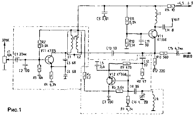
Offer readers the downtime transmitter video. It can be connected to any VCR, or computer on LF output. Operates the transmitter in the meter range (5...channel 9), the supply voltage is 4.5...6 V. diagram of the transmitter shown in Fig. 1.

Transistor VT1 is assembled mixer oscillator with FM conversion of audio frequency 5.5 MHz (6.5 MHz). The frequency of the local oscillator depends on the capacitances C4, C5 and inductors L1, L2. On VT2 performed heterodyne carrier, whose frequency depends on the choice of TV channel. Ha R12 is mixing the video signal and FM sound carrier and the desired channel. Next on VT3 signal is amplified and transmitted to the antenna.
The necessary level of 3H is set by resistor R1. LI, L2 are wound on the coil imported from the radio to which the configuration item is a ferrite Cup. L1 contains 23 round wire PEL-0,1; L2 - 24 turns of the same wire.
L3, L5 wound on the mandrel 4 mm and contains 5 turns of wire PEL-0,35. L4 - 4 mm mandrel, contains 4-loop wire PEL-0,35 wound coil to a coil. After setting up this reel, it is desirable to pour paraffin. As an antenna you can use a piece of copper wire of length 20 to 50 cm or telescopic antenna from any radio.
In Fig.2 shows a printed circuit Board of the transmitter. In Fig.3-arrangement of elements.
With proper Assembly design begins to work immediately. Should you switch the TV to set it to the desired channel (in my case - TV-6). The setting is made by items 13 and L4. Next, you need to configure elements L1, L2 (C3) sound carrier on better TV reception audio signal.

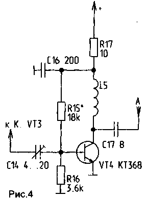
Fig.4
If you find insufficient transmitter power, it is possible to assemble the amplifier circuit shown in Fig.4. Only in this way will have to change the drawing of the PCB and instead of C14 to install trimmer capacitor, which will later be tuned in resonance to the maximum of the transmitted signal. For more information on setting this cascade is given in [1]. In conclusion I want to note that this transmitter has been tested on TVs 4th and 5th generations and showed a good result. His power is sufficient for the apartment. Radius - 5...8 m, it can be increased when using the optional cascade MIND.
Literature
1. F. Dukes. How to build the simplest TV repeater.//Amateur radio operator.-1994.-M 7.-S. 4-5.
Author: V. Papko, Vitebsk obl., g/n Ushachi; Publication: N. Bolshakov, rf.atnn.ru


