Adding a simple VCR attachment, you can turn it into a small telecentre and to establish local television programming in the small village, the village, the children's camp. A complete block diagram of the device shown in Fig.1. Performed common parts, does not require any changes in the VCR and the TV.
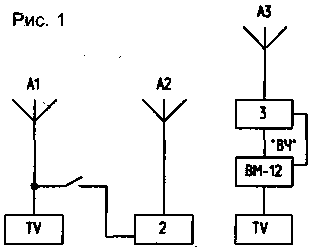
In domestic a VM exit "RF", it allows you to produce broadcast programs on the antenna input of the TV, the included 6-channel meter band. Strengthening the signal, you can transmit it to a distance of several hundred meters. Admission is conducted on an ordinary TV, which uses a separate antenna A2, oriented to the transmitting antenna A3. The latter is preferably set as high as possible, for example on the roof of the house. The received signal for signal reception is enhanced antenna amplifier, schematic diagram of which is shown in Fig.2.
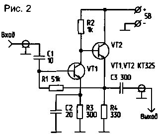
All connections when mounting the amplifier must be of a minimum length. Power - source with low ripple factor, otherwise the TV may occur moving or standing horizontal stripes. It is best to power the circuit from the power supply unit to the TV via a small voltage regulator. The amplifier works well on all 12 channels of the MB range, so it can be used for enhancing the signals of local television. The transmitter is connected to "RF output" VCR, TV - through interfacing the device to its outputs VIDEO and SOUND.
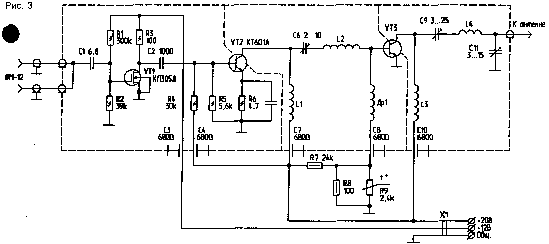
Preliminary cascade of the transmit amplifier (Fig.3) is assembled at the field VT1 transistor with a gain of about 10.
(click to enlarge)
At the entrance stands a capacitor C1, having a very small capacity, so the device practically does not change in the output signal of the VCR. The signal is amplified by two stages of linear power amplifier. In the first, with the greatest gain, used the VT2 transistor operating in class A. the Output stage (gain power equal to 5) performed on the VT3 transistor with high electric strength and good linearity. For temperature stability of the cascade is applied to the thermistor R9, mounted on the radiator, near the VT3 transistor. In addition, cascades separated by screens.
The transmission coefficient of the device is about 40 dB. The amplifier thus develops an output power of about 2.5 watts. Its output is designed for connecting a load resistance of 75 Ohms. When mounting the capacitor C1 is directly soldered to a Central conductor of the cable coming from the VCR. The capacitor must be of a minimum length, and all other connections. To ensure stable operation of the base circuit of transistors is separated from the collector. The transistors VT2 and VT3 are placed in the holes on the radiator and next to the transistor VT3 is set to thermistor R9. The other parts are assembled on a printed circuit Board from a two-sided foil fiberglass, mounted on racks on the radiator. Foil one side is used as the screen. Hole parts must be razzenkovannoe. The screens between the base and collector circuits of the transistors are also made of foil fiberglass. They must be connected to the shared screen scheme.
The amplifier is applied to the following details: thermistor - type AP-1, trimmer capacitors C6, C9, C11 - type CT-21V. Choke DR1 wound on a resistor is 0.25 a resistance of 100 ohms wire sew-1 0,12 in a row before filling, about 30 turns. Coil - frameless and coiled silver plated wire with a diameter of 1 mm, L1 contains 3 coils, the outer coil diameter is 10 mm, the winding length of 6 mm; L2 contains 4 of the coil, the outer coil diameter is 8 mm, the winding length of 8 mm; L3 contains 3 coils, the outer coil diameter is 8 mm, the winding length of 5 mm; L4 contains 4 of the coil, the outer coil diameter 10 mm, length of winding is 8 mm. to Feed the amplifier from any regulated source, providing at a voltage of 20 V, the current of about 0.5 A, amps At 12V is about 80 mA. For the receiving antenna A2 is better to use a 5-element antenna of type "wave channel" (Fig.4).
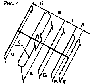
Its dimensions are given in table.1
Table.1
and
b
in
g
d
e
And
B
In
G
D
915
350
215
205
215
10
810
730
725
710
60
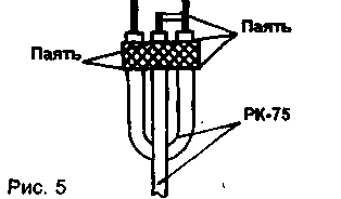
Material for antennas are aluminum or dural tube. The most suitable diameter for the bearing of boom -18...22 mm, for vibrators - 10...14 mm Cable with wave resistance of 75 Ohm is connected to an active loop to the vibrator through U-knee (Fig. 5). Knee length - 530 mm Place of connecting the cable to the vibrator should be insulated by covering it nitro or epoxy.
The transmitting antenna A3, if correspondents are located in one direction from the transmitter may be the same antenna that is used on the receiving side (Fig.4). If correspondents are located on different sides of the "telecentre", it is better to use so-called "circular antenna (Fig.6). The length of dabela E1 and E2 are chosen equal and minimal.
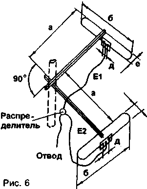
The antenna dimensions are given in table.2.
Table.2
and
b
e
d
360
720
90
60
Vibrators are made of aluminum or duralumin tubes with a diameter of 10...16 mm. To harmonize them with cables E1 and E2 is also used U-knee (Fig.5). Diagram of the dispenser shown in Fig.7.
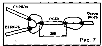
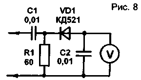
For load matching, the used section of the cable with a characteristic impedance of 50 Ω (RK-59-4-13, RK-50-2-13, RK-50-2-11), length 280 mm, and to decrease with a characteristic impedance of 75 Ohms with a low linear attenuation, for example RK-75-9-12 and RK-75-9-13. Setting prefixes begin with the transmitting amplifier. First tuning resistor R1 sets the current of the transistor VT1 within a 5...7 mA. Then move on to adjusting the contours of L2 C6 and C9 L4. Connect the amplifier input to the "RF out" on the VCR, and the output of the transmitting amplifier, connect the meter average power MZ-5A. If this is not available, assemble the circuit shown in Fig.8, and alternately adjusting the rotors of the condensers C6 and C9, achieve maximum readings. Then connected to the output of the transmitting amplifier working antenna.
Around the loop of the vibrator of the antenna coil 2...3 coils of wire (any) and collect scheme, shown in Fig.9.

After adjusting communication with the antenna (tuning capacitor C 1 is 1), the antennas are oriented to each other, and if the transmitting antenna is circular is directed only to the receiving antenna. If necessary, adjust the channel selector of the television receiver 6 channel. You can start the transfer.
Author: V. Chudhary, Tyumen region, Berezovsky district, p. Igrim; Publication: N. Bolshakov, rf.atnn.ru


