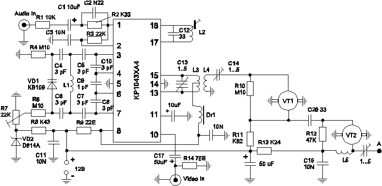
A schematic diagram of a transmitter placed in Fig.1.
The transmitter operates in the UHF range (UHF) and is built on one chip and two microwave transistors. It ensures the perfect quality color picture at a distance of about 50 m. the Maximum range depends on the sensitivity of the TV, antennas used, and a color image is 300 m, and black and white - more than 500.

Coils L1, L4, L5 contain 1.5 round (ring down with the conclusions) of PEV 0.5 mm, and the coil L3 2+2 turns of the same wire, and consists of two halves, between which is placed the coil L4. The gap between the coils L3 and L4 of about 1 mm. Coil L2 is taken from the contour of rejection of sound from any TV. The contour L2 C12 tuned to the subcarrier frequency sound 6.5 MHz, therefore, the capacitor C12 may be another tank, which was part of a circuit of the TV.
Details of the transmitter is placed on the circuit Board of foil on one side of the fiberglass. A schematic diagram is drawn so as to it was easy to draw the PCB Board. This should take into account that the width of conductor shall not be less than 1 mm. Conductor "mass" is solid fill the free space of the Board, at a distance of 1-2 mm from the other conductors. Important to pins 5 and 14 connected with each other under the chip and with a mass the shortest way. One should strive to see the rest of the guides were minimal length. Mandatory welds both of emitter UHF transistors.
Fee top is closed by a brass screen height of 20...25 mm with holes opposite the adjusting elements (R7, C13, 14, 21, L2) and output antennas. Screen propivaetsya the contour of the bottom of the Board. To install the antenna on the Board raspivaetsya latonia sleeve with internal thread M2, where and wrapped the probe antenna. The antenna is a piece of bare copper wire from lighting wire cross-section 2.5 mm2. Antenna length is determined experimentally and is approximately 30 cm.
The configuration comes down to setting point modulation resistor R7 (this changes also the operating frequency) by the absence of green kotorov and pink "Tyagunov" on the image contours and matching with the antenna. In the last instance is configured the contour L2 frequency 6.5 MHz (on the ear for pure sound transmission).The output signal of the transmitter must have sufficient power to receive "input" of the TV from a distance of about one meter.
Publication: N. Bolshakov, rf.atnn.ru


