Offer directional coupler designed for use in the device the television division of the signals received one antenna.
Very often in practice, television receiving a situation arises, when one antenna receives several television signals having different level. When connecting to antenna TV, quality the received signal is usually satisfies the consumer. It provided parameters television receiver (sensitivity, selectivity, dynamic range).
Other the situation is obtained if it is necessary to amplify the signal, received by the antenna, for example, to feed the system community reception when the signal level from the antenna insufficient to feed on channel amplifier. The use of broadband amplifier for a few TV channels always leads to disastrous results. Intermodulation distortion in the amplifier "score" the weaker channel, so that the presence of this channel remains only guess. The most the correct solution in this the situation is to install separate antennas for each channel. However, in many the installation of separate cases antenna on impossible a variety of reasons.
For to clarify further reasoning take a specific example electromagnetic environment. At the antenna output of the 3rd TV range have:
- level 7-th channel 77 dB µv;
- level 9-channel - 52 dB microvolts.
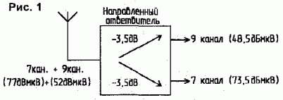
For submission signals on a channel amplifiers, they must to divide, and the signal of the 9th channel - strengthened further, so as for most channel amps nominal input level - about 70...80 dbµv. Using chiropolos splitters with attenuation in the forward direction by 3.5 dB, obtain the distribution of signals, shown in Fig.1.

As can be seen from Fig.1, division signals it is not entirely successful, since the signal level of the 9th canal additionally falls on 3.5 dB, and the ratio signal/noise deteriorating. In addition, such splitters are isolation on output 22...26 dB, not always sufficient to stable operation of such system.
For the optimal solution of this the task was made directional coupler for the scheme from [1]. Features separation of signals is given in Fig.2.

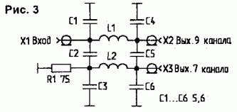
Tap has the isolation moves you in the frequency range over 46 dB, which is significant extent weakens the hit signals from the output to the input channel amplifiers, and the ensures stock sustainability at large the amplification of signals. Scheme the tap shown in Fig. 3.

Coils L1 and 12 - frameless, they contain 4 turns of wire sew-2 00.7 mm, the diameter of the coils - All 5 mm. capacitors-type CD-1 or K10-17. The input and outputs the calculated for connecting a 75 Ohm load. Setup from-vetices is made coils on the maximum transition the attenuation between the outputs from the the frequency of the 7th channel.
Common structural scheme generating signals for feed channel amplifiers shown in Fig.4. As can be seen from Fig. 4, the signals of the 7th and 9th channels, despite the difference in levels at the antenna output, aligned given given device and are reduced to a level of about 70 dbµv, which is enough to feed the channel amplifiers.

On this the scheme was made more a dozen devices that showed good repeatability and high the quality of the received signal. Such directional overviel (Fig 3.) you can apply in various devices (low-power the transceivers, the adders, the adders).
Literature
Author: S. Novikov; Publication: www.cxem.net


