


")

Model selectors television channels, produced by JSC "Minsk instrument-making plant" with the trademark "BELVAR", are listed in table. 1. In it also specifies the functionality of the selectors, some circuit-design differences, counterparts. It should be added that all selectors there is no output for the supply voltage APCG and all models are equipped with antenna socket type IEC.
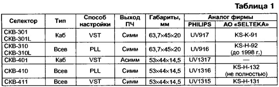
By early 2000, many of the once popular model selectors plant (СSW-101, СSW-103, СSW-151, СSW-201, СSW-210) were discontinued. Nevertheless produced selectors adequately reflect the main directions of their development: cable (KAB) or all-wave (all), with the synthesis of voltage (VST) or frequency synthesis (PLL), with a supply voltage of 12 V or low-voltage (5 V).
The symbol selectors historically. It consists of an alphabetic character reduction СSW (all-wave channel selector) and (hyphenated) three digits. First of them initially served to distinguish one series of developments from the other, for example, СSW-101, СSW-201. But recently in connection with the development low voltage selectors this figure were used to indicate voltage power: 3 - 12, 4 - 5 V. This figure now characterizes the type of selector: cable models assigned the number 0, and all-wave - 1. The latter figure reflects the tuning method used in the selector: for PLL - 0, a VST - 1. Options execution selectors СSW-301 and СSW-310 with elongated antenna input of 32.2 mm complement the letter L (Long).
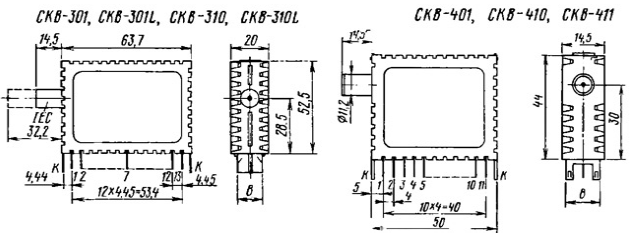
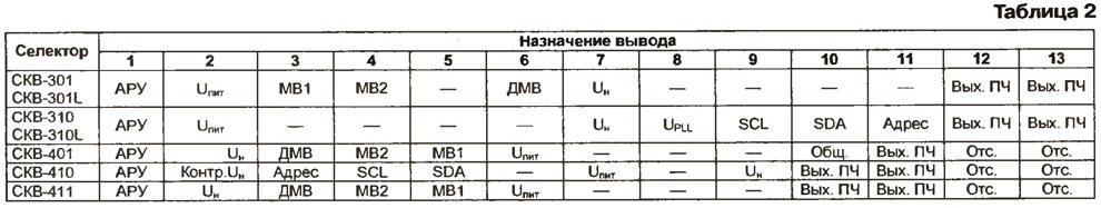
The appearance of the selectors and their basic dimensions sketchily shown in the figure, and the pin assignment is shown in table. 2
It should be borne in mind that the countdown conclusions all of the selectors is from the antenna Jack. Contacts To corps serve to connect the common wire. The table used symbols: UnviT - voltage supply; and a fifth voltage settings; Counter. UH - conclusion voltage control settings; UPLL - voltage power synthesizer 5 V.
(click to enlarge)
Model three hundred series are made according to European standards the standardization of design: step pin location of 4.45 mm, symmetrical if output. Four hundredth series complies with new international standards: the step of the pin 4 mm at their maximum number is 11.
The breakdown into sub-bands of the received frequency cable models selectors (СSW-301 .СSW-401) differs from that in [1] so that all cable channels concentrated in the sub-band V. Subbands conclude the following frequencies (channels), MHz:
- A - 48…111 (1-5);
- In - 111 …300 (K1-K18, 6-12);
- C - 470…862 (21-69).
The sub-band for all models of extended selectors on the 69th channel Therefore in the last two sub-bands b and C will be increased "sharpness" settings. Therefore, more stringent requirements should be made for voltage stability settings and smoothness of change, as well as to the system APCG.
Basic electrical parameters of the selectors are summarized in table. 3. In values given in parentheses refer to the sub-band V. it Should be noted, the gain patterns СSW-301 and СSW-310 in the sub-band In a markedly lower than in the other sub-bands. As a result, the flatness in all the range of accepted frequencies in these selectors reaches 8…9 dB, though within each sub-band (A, b or C) does not exceed 4 dB.
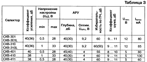
A comparison of models "BELVAR" according to parameters such as depth automatic gain control(AGC) and the rejection in the sub-band In which is equal to 50 dB (in sub-bands A and C - 60 dB), with similar or close models of production of JSC "SELTEKA" [1, 2] shows that they are some inferior to the last. However, the selector СSW-411 favorably with the economy: its current consumption is 20.. .25 mA less than similar selector KS-H-131 (JSC "SELTEKA").
The lower limit of the voltage settings of the selectors selected VST is equal to 0.5 V (vs. 0.7 V for analogues) that must be considered when installing them into modernized the TVs. This is especially true of devices that replace the selector SC-M-24 that has a lower voltage limit setting 1 or more Selectors with the synthesis of frequencies(R) presents two models, a characteristic feature of which is the lack of READING mode. The first of them (СSW-310) - the most developed model. It provided the installation (programmatically) step of adjustment, equal to 62.5 and 31.25 kHz. The speed of adjustment in the selector slowing down at the approach to the broadcasting channel to reduce the residual detuning. The selector is applied to the synthesizer MS company MOTOROLA, which implies the use of processor control.
Specified in table. 1, as an analogue of this model, the selector KS-H-92 by the beginning of 1999. was upgraded, resulting in its functional capabilities and system management has changed [2]. Therefore, if a strict approach to interoperability to be considered analogous to the embodiment of the selector that released to its modernization.
In table. 4 shows two control byte in the RECORD mode, the selector СSW-310.
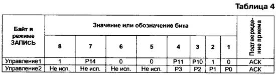
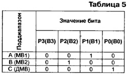
Changing the speed of adjustment provides a bit P14: 0 leads to slower. Tuning step set bits P11 and P10. If they the same (both 0 or 1), the shift step is 62.5 kHz, if different (combination 01 or 10) - 31,25 kHz. For switching sub answer bits RZ-P0 in accordance with table.5.
Information about the byte address and the software of the divider and also about the States of bits of the address selection (MA and MAO) are available in [2, tab. 5 and 6] and can be used for this selector.
Model СSW-410 - one of the latest developments. You can set three the step value adjustment: 62,5; 50 and 31.25 kHz. The rest of the functions like this same as the previous model. Since the supply voltage selector is equal to 5 V, separately to provide power to the synthesizer (Upll= 5 V) is not necessary and conclusion 2 the selector used to control the voltage settings. The selector is applied synth TSA5522M.
It should be borne in mind that the starting material [3] the selector UV1316 stated in as a counterpart, as well as model KS-H-132 have a broader functional opportunities. Replacing them on the selector СSW-410 are possible, but only with the loss regime READING and the lack of a five-level ADC (ADC).
As to control the selector СSW-410. it is in the RECORD mode has not differences from the one considered in [2] analogues PHILIPS and JSC "SELTEKA".
The scheme and the inclusion of selectors (in General form) is presented in [1]. Recommendations for the application of models with symmetrical if output and to harmonize them with blocks radio SMRK-1-5 (SMRK-1-6, SMRC-2-1) are given in [4].
Literature
Author: A. burkovsky, St. Petersburg