Now turn on the TV. On the screen you should see a raster, but no picture, since the radio channel is disconnected the antenna and the control circuit. On MRCC under power, and it allows you to test its functionality, the Appearance of the raster means no serious faults in MRCC. Check the values of the supply voltage+220, +12, +8, +5,6 In and on the conclusions of chips. Noticing that they are different from these schemes by more than 10... 15 %, check the correct installation of the respective circuits. In TVs with UVP types of MRAs, CCA speaker should appear noises, and when not too disordered exemplary circuit and sound the previously tuned program. The TV comes with ICSU noise will not be up to the configuration of the exemplary circuit of the SOS signal is not produced and noiseless system settings closes the path of the sound.
If all voltages were within normal limits, make (turning off TV) in the sit and BOO the changes shown in Fig. 7, connect to MRCC cables X5 (A9), XS (A8), X7 (A13), X10 (A13). Cable X5 (A3) yet should not be included. You need to turn on the TV, to verify the presence of raster and, in his absence, to test the brightness and contrast, the serviceability of the circuit adjust the brightness.
Having received the illumination of the screen, verify the presence of noise or ghosting of the image. After that remove from pin 10 of connector X5 (A3) plug with resistors R301, R302 and turn the connector X5 (A3) in the SRP, which will translate blocks of horizontal and vertical sweep on MRCC (before that they were controlled by the signals from module SRM and MRC). Make your changes (by turning off the TV) to SRP (A3) according to Fig. 9. Then turn on the TV and check the availability of the raster.
Configure exemplary circuit. In the presence of high-frequency generator, follow the recommendations in [2]. There is no such generator tuning coil L3 perform, based on the assumption that the exemplary circuit in skim MRK was previously correctly configured on the frequency of 38 MHz, and the system presets the DIP exactly worked out the voltage for the channel selectors and they were configured on the load-bearing signals from television transmitters. Then, without changing the adjustment UVP and not including the system APCG, you need to configure the exemplary circuit MRCC to the same frequency, which is configured similar to the circuit in the MRC. To do this, connect a DC voltmeter to the point X1N MRCC and adjust the coil L3 to a voltage of +3.5 V at the specified point. When using SVP, USU exemplary configuration of the circuit is completed.
When using the sit resistor R22 (see Fig. 2) in the sit, get a voltage of +2.5 V at the point XN3 in the module. Adjustment exemplary circuit should lead to the emergence of synchronized sound and image.
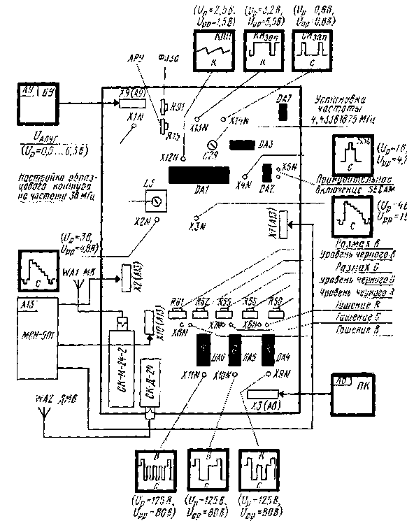
Check the oscilloscope according to the shape and amplitude of signals during all control points, for which in Fig. 16 illustrates their appearance in case of vertical colored stripes (Up - constant component of the signal, Upp - scale signal). In the absence of a signal at some point find reason using the schemes and description.
Variable resistors CCA or MRAs (system settings module ICSU) achieve higher definition of acceptance test tables. Set up the AGC level, ensuring the absence of noise and distortion of the vertical lines on all programmes. Adjust the size, linearity and centering frames built with resistors of the module MK-1-1 and phase resistor MRCC.

Fig.16
Achieve white balance. In position, the brightness at the minimum level by resistors R50, R56, R62, get in control points X9N-X11N voltage level 125+5 V. Then, when the tubes LK, LK-Z adjustable resistors R3, R5, R7 in chains accelerating voltage get the white balance on the minimum brightness level. If this fails (upgradeable TV has a picture tube with reduced emission cathode), to achieve the white balance at this level of brightness can adjustable resistors R50, R56, R62 with any type of microscope.
Then increase the brightness to a normal level and adjust the resistors R55, R61 first set the amplitude of the signals at points X10N, X11N equal to the magnitude of the "red" at the point X9N. Next you need to adjust these resistors to obtain white balance normal level of brightness. Repeat the adjustment several times to save the white balance at any level of brightness. Check the focus of each of the beams of the picture tube separately, if necessary, it can be improved by appropriate adjustment of the resistor on the CRT Board (only for SC/C), and then check and adjust the white balance.
The next step is adjustment of the system current limit rays. You need to attach a voltmeter to the output 25 of the chip DA1 MRCC and install the adjusting resistor R20 module in horizontal position at which the voltmeter begin to decline.
Check out the work MRCC from external video sources. Plug X4 (A3) MRCC from adjusting the cable and include it in the SRP (A3). To remove modules MRC and MC with the chassis of the TV, set it MRCC and finally check it out.
If when creating a module having difficulty, refer to section 3.2.3 of the manual [7], where a set of possible malfunctions and ways of their elimination.
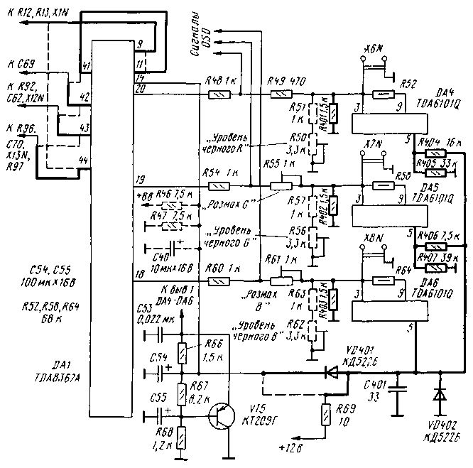
The use of chip TDA8362A instead TDA8362 allows you to enter in the module auto-install dark currents of a CRT (automatic white balance (ABB). The changes that need to be made for this in the previously discussed circuits shown in Fig. 17. They are associated with differences in the Pinout of the chips and the introduction of ABB.

Fig.17
For the correction of differences in cocalico is necessary to remove the conductor connecting the terminals 9 and 11 of the chip DA1, and to connect pins 11 and 41 (removing circuit shown in Fig. 17, the dashed line, and the newly - thickened). Chain APCG connecting elements R12, R13, X1N with the output 44 is connected to the pin 9 of the chip. Chain Kisap from the point of connection elements C70, R96, R97, X13N switch with output 43 to the output 44. The circuit of the generator personnel saws from the elements ر62, R92, the X12N presedinte with output 42 output 43, and a chain personnel OOS with capacitor C and pin 10 of connector X5 (A3) connected to the output 42.
For the introduction of ABB you need to change the chain signal R, G, chip DA1 to DA4-DA6 and arrange on pin 14 of the chip DA1 measuring pulses from sensors ABB (they are displayed on the conclusions of the 5 chips DA4-DA6).
In circuits the signals from the terminals 18-20 circuits DA1 to the findings of the 3 amplifiers DA4-DA6 exclude the resistors set the level of black R50, R56, R62, and instead of the resistors R51, R57, R63 install R401-R403. The chain of transmission signals
ABB incorporates elements of R404-R407, VD401, VD402, S. Resistor R69 from the point of connection elements R66, R67, S (see Fig. 6) switch to the junction point of elements VD401, VD402. S, R404, R406. From pin 11 of the chip DA1 off (useless) resistors R46, R47 and a capacitor C40.
Resistors R404-R407 set chips near DA5, DA6, where they provided a place on the Board. Details S, VD401, VD402 placed in the free space between the chip DA6 and selector switch IC-D-24.
Adjustment system ABB in this case, a similar procedure easier when you use chips TDA8362. White balance with minimal brightness (dark) is set by ABB automatically. The optimal white balance when the brightness (bright) adjust trimmer resistors R55 "G Scale" and R61 "Swipe In".
Need a little clarification on the economic side of the proposed alteration. The module will cost about 110 rubles (TDA8362 - 35 roubles, TDA8395 - 18 rubles, TDA4661 - 14 rbl., TDA6101Q - 5 rubles., as well as transistors, capacitors and resistors - 30 rubles) prices store CHIP & DIP (spring 1998). The acquisition of more advanced channel selector need to spend 50...80 roubles Replacement keypad DIP synthesizer voltage requires about 110 rubles (ICSU-501, block a receptionist reception of the BAP-45, remote controller RC-5). Therefore, the alteration will cost 110...300 rubles depending on the degree of refinement.
And what will be the resulting?
1. Increased sensitivity of the TV and the effective suppression of noise in weak signals, you acousticity interlaced.
2. Multistandard and Multisystem (PAL, NTSC, SECAM-BG/DK, PAL-BG/DK), and if need be, NTSC 4,43.
3. Increase reliability by reducing the number of components used, the inter-module connectors, controls.
4. Protection of the tube from burn-through.
5. Decrease (although not very large) power consumption.
6. When installing the voltage synthesizer TV acquires all the features characteristic for the devices of the fifth generation.
In conclusion, we note that the new modern TV fifth and sixth generations, having a picture tube with a diagonal size of 53 cm, was worth 2.5...3 thousand (until August this year).
Literature
- Lukin N., Jankowski S., Koryakin-S. Chernyak Nodes and modules of modern TV sets. A series of "Repair", vol.5. - Kiev-Moscow: Science and technology & salt,1996.
Author: V. Brylov, Moscow; Publication: N. Bolshakov, rf.atnn.ru


