Set MRCC in TVs OPCT pretty simple: you have to remove the blocks BRC and BC and post MRCC instead of DBK by doing small changes in other blocks. This substitution leads to a very effective result is abolished two of the most cumbersome of the three blocks of the TV, greatly reduced power consumption, more than twice reduced the number of tubes. All this greatly improves the temperature in the Cabinet - his Achilles ' heel, the root cause of frequent fire. Instead of the connectors shown on the previous diagram on the Board MRCC socket set S and attach the cables to the plugs Sa, Sa, Sa to supply the necessary voltages and signals. Cable S connecting with DBK BC, is removed as unnecessary. Instead of a tube USC you should use the module UM1-3 from OPENCT. Used in TV the selector drum SC-M-15 that has a very low gain Ku (8 dB), replace SC-M-24, SC-D-24 or more modern with the installation of a CIP type CCA-1-15 or the sit-501.
A significant reduction in current consumption in all power supply voltages requires the selection of the values of damping resistors in the block header to return to the regular nominal voltages. The +12 V voltage ULPORT is formed in the control unit of voltage +24 V with stabilizer from the quenching resistor and Zener diode DB. This node is too weak to power MRCC and must be replaced with a unit designed for higher current.
If the owner upgraded the TV's meet the previously adopted parameters of the module to accept only system SECAM and PAL standards
In and G in the TV ZUSTST with selectors SC-M-24-2, SC-D-24, it is possible without any changes to collect MRCC on previously considered concepts.
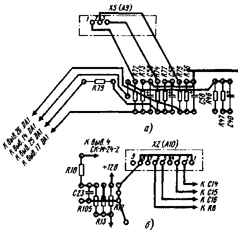
Printed circuit Board module shown in Fig.12.and Fig.12.b
It is suitable for CIP of any type with the following reservation. When using the sit-501 on the Board must be present all the traces shown in Fig. 12,a and b, solid and dashed lines, as well as all the parts except the resistor R78.
When using UVP types of CCA, SVP traces, shown by dashed lines, do not, and the details VD1, VD5-VD7, R35, R81 - R84, C23, connector X7 (A13) is not set. Connector X10 (A13) is replaced by X5 (A9). The changes that need to be done on the PCB depicted in Fig. 13: resistors R46, R47, R79 and capacitor C40 are the same as in Fig. 12. Capacitors C-S place in a new way, together with the resistors R72-77.
Instead of connector x2 (A13) install connector x2 (a10). When the terminals 2, 3, 5, 6 include similar contacts 3-6 connector x2 (A13) as shown in Fig. 13.b.
If you wish to use any of the previously listed modifications useful to have a complete schematic diagram of the future module based on the previously discussed schemes and recommendations, selecting from them the necessary elements. Then make the necessary changes in the circuit Board of the module (in the pattern of printed conductors).
Details of the module is placed on the Board of two-sided foil fiberglass 2 mm thick. Trace trace module is executed based on the location of the findings of the details in the grid 2,5x2,5 mm and reduced the distance between the pins TDA8362 (1,778 instead of the usual 2.5 mm). It was forced to withdraw latest on both sides of the Board. In the detailed description of the chip TDA8362 [1], with which you should explore, particularly emphasized in the trace fees to provide for the minimum length of conductors between the terminals 28, 29 of the chip and TDA8362 terminals 11, 12 of the chip TDA4661, as well as from the common wire (pin 9 IC TDA8362) to the capacitors connected to its terminals 12, 33, 42. Pin 3 of chip TDA4661 (common wire, its digital parts) and the capacitor C32 connected to the common wire, single conductor (digital ground) connect to pin 5 of connector X4 (A3).
In module selectors used channels, remove from ISC Board upgraded TV. Resistors - MLT with ratings for a number E24 and a tolerance of ±5 %. All the adjusting resistors - SDR-38b. Capacitors with a capacity of up to 0.22 µf ceramic K10-7 or K10-176 with a working voltage of at least 16 and a tolerance of ±20 %. Capacitors C7, C9, S-S, S capacity of 1...10 UF - tantalum K53-3, K53-34, K53-35, the remaining capacity 1...470 µf oxide K50-6, K50-16, K50-35. Capacitors C41, s, S - ceramic KD-1, KD-2, km-3, or ceramic K21-8, K21-9, for a voltage not lower than 250 V. the Capacitors C44, C48, C52 - ceramic K10-47 or polietilene-retaliate K73-17, K73-24, K73-30 a voltage not lower than 250 V. Coils L1, L2, L4 - EU-24; 13 of the circuit 11 or L2 from SMRC-2.
Chip TDA8362 can be replaced by its complete analogue TDA8362N3; TDA8395 - chip TDA8395P or ILA8395; TDA4661 chips TDA4665, TDA4660. If you use the latter to its pin 13 is additionally connected resistor MLT-0,125 nominal 1 MW, connected to the second output with the common wire.
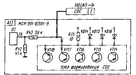
Synth stresses the sit-501, the sit-501 -4 include in the socket of the regular module connectors, without changes in their cocalico. Depending on the location of the sit in the Cabinet might need a lengthening of the connecting cables. The synths sit-501-8, the sit-501-9 can be used after slight modifications. The SOS signal in these models served on the microcontroller is not with output 2 connector X10 (A1), as for the sit-501, the sit-501-4, and from its site of formation, assembled on the transistor VT14-VT18. In synthesizer make changes according to the scheme in Fig. 14. The transistor VT14-VT18 no longer needed. For disconnection from the power supply circuits and outputs should unsolder the resistor R75 (10 Ohms) and diode VD14-VD16 (CDB). Resistors R42. R43 should be replaced with the values of 620 and 510 ohms respectively. The output resistor R43 is connected by wire with the free socket 2 plug connector X10 (A1). The numbering of parts is given according to the original scheme of the TV "Horizon CTV518".

Fig.13
The establishing module is recommended in the following order.
Check and if necessary adjust the voltage at the power module and configure the TV to accept the program when the system is APCG.
Check with an ohmmeter power supply circuit module. Circuit resistance +220 V relative to GND should be about 500 ohms, the circuit +12 V - 750 Ohm, chains +8 V and 5.6 V - 700 and 600 Ohms respectively. With these and further measurements should strictly observe the polarity of the ohmmeter.
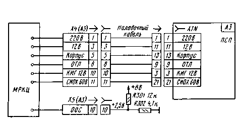
To remove the back wall of the TV, place MRCC on the table next to the TV. Keeping all the modules of the TV in place, disconnect the cables x2 (a10), X9 (A9) from the MRC unit of the TV and connect to MRCC. If your TV using the synthesizer of sit, it will be the connectors x2 (A13), X9 (A9). On the plug connector X4 (A3) MRCC to put the socket up cable, assembled according to the scheme shown in Fig. 15. Plug this cable connected to an outlet X1N Board SRP (A3). To pin 10 of the plug connector X5 (A3) is connected shown in Fig. 15 resistors R301, R302, to apply temporarily the voltage of +2.5 V at the output 43 of the chip DA1. Other connectors will be connected to MRCC later. To remove the channel selectors with the MRC unit, to install them on the Board MRCC, connect the antenna.

Fig.14

Fig.15
Literature
- The brylov V. 68 programs in TVs ZUSTST. Radio, 1997, No. 11
Author: V. Brylov, Moscow; Publication: N. Bolshakov, rf.atnn.ru


