


")

Many computer games require management not only joystick, but the introduction of the commands from the keyboard. However, to keep to yourself while playing both of these the device is very inconvenient. Using a programmable logic array (PLA) RT, the author solved the problem by replacing the "keyboard" command combinations clicks of the joystick.
Games programs for the ZX Spectrum is constructed, as a rule, such a way that after launch they are not included automatically in the control mode joystick; you have to press a few keys. The need to use the keyboard sometimes arises in the course of the game. For example, to to start a new session, replace the game, you press the button initial setup. And this means that the player with the joystick in his hands for a long time to move away from computer, to sit in a chair or lie down on the sofa. In order to push one or two keys frequently needs to step up to the computer.
Some games are not meant to manage only the joystick. Have intensive keyboard use that it quickly fails. To the same keys that control the direction of movement of the figures and shooting, there are badly chosen (for example, are located on the keyboard in a row) that often affects the result. It would be tempting, not changing programs, to transfer to the joystick management and such games.
Today the most common push-button joysticks, having five conveniently placed buttons to indicate the four directions of movement and shooting. For other operations (enter control game characters) to use all sorts of combinations of button presses. But the solution to this tasks in the traditional way by means of chips of small and medium integration leads to the creation of too expensive and complicated device.
In the industrial equipment are widely used as yet little known to radio Amateurs the PLA chip specifically designed to implement complex combinational logic. One of them is RT can simultaneously calculate 8 logical functions of 16 input variables, the latter may enter a Boolean expression in 48 different combinations. In structure it is similar to EPROM the same series 556. To implement the desired functions from the programmer calcine fuse links on the chip of a chip. The method of programming the functional diagram of the programming and schematic diagrams of the blocks can be found in [1-8].
Revised scheme of ZX Spectrum shown in the figure.
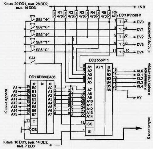
The joystick (via inverters chip DD3) and keyboard remain connected to the computer in the usual manner and continue to perform its functions. The contacts of the buttons to SB 1-SB5 additionally connected to the inputs A1-A5. and the lines A8-A15 address bus CPU - with inputs A7-A14 PLA RT (002). Input A6 left free. The chip outputs 0D2 (open collector) is connected to the keyboard port (KL0-KL4) parallel to the line and the initial setup.
You need to consider that in many embodiments, the computer ZX-Spectrum address bus the processor is overloaded. Therefore, to connect with her keyboard and more load (inputs PLA) is recommended via a bus driver KR580VA86 (DD1). Sometimes he is already in the computer, for example, if it is connected to the drive.
Such a buffer will increase the reliability of the keyboard. The fact is that to reduce the load on the address bus, the developers of the computer connected to the inputs of a keyboard port with the power source through resistors large denomination (15 kOhm). As a result, after the key is released, the parasitic capacitance recharge too slowly which leads to false readings of the keyboard status. In some games this the defect manifests itself as a chaotic move the cursor on the screen spontaneous switching of modes. After you install the tire and driver reduction of the values of load resistors to 1 kω similar phenomena eliminated completely.
When the switch SA1 is open, the PLA outputs are in high impedance condition, and it does not affect the operation of your computer. Closing SA1, combinations pressed joystick buttons you can duplicate the actions of some keys. It is due to the fact that "sewn" in the PLA logic function repeats on relevant input keyboard port status of one of the bits of the address simulating thus the connection of these circuits the contacts button you press.
The program of the firmware PLA are shown in table. 1.
From 48 existing in the matrix elements 16 used 30. An example of the preparation of the programming codes element simulating a keystroke "C", are shown in table. 2.
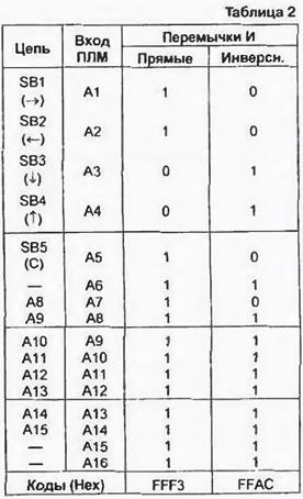
You are required to submit the signal from line A8 data bus (input A14 PLA) on the line KL3 keyboard port (exit B4 PLA), if the button "Right". "Left" and "Shooting" are pressed together.
In metaprogramming PLA each of the inputs A1-A16 is connected with the corresponding the input element 16 through the two fuse links, in the chain of one of them there is an inverter. If you burn through "inverse" jumper, the argument will go on the entrance element And directly, but if "straight" - proinvestirovany. Burnout both jumpers generally eliminates the argument of the function can be realized. In binary digits are the codes programming remove the jumpers represent logical 1.
In our case, pressed the buttons to correspond to a logical 0 on United with them, the PLA inputs. In order to implement And need to invert. removing the "direct" connection. And in the discharges associated with buttons, in this combination is not pressed, delete "inverse". Then ask used line address bus. As an active logic level on her low, the corresponding digit of the code is also removed from a direct jumper, leaving "inverse". It remains to disable unused inputs by removing both jumpers in their the discharges.
Matrix OR consists of eight (one for each output) elements RI, inputs which jumpers are connected to the outputs of the matrix I. Thus, the output each element 16 has eight jumpers; it burns it disconnected from the corresponding element II, and hence the output from the PLA. The exit B1 corresponds to the youngest, and B8 is the MSB of the code programming. To we need to leave the connection with the release of V4, we will set code 0F7H. If programming was a mistake or need to replace one the function of the other, calcine all jumpers (code 0FFH). completely disabling unnecessary element And exits. Instead, it programming are one of the unused. While such elements, the operation can be repeated repeatedly, improving and complementing the algorithm of operation of the joystick.
Please note that the button "Left" simulates a keypress "5", independently the state of the button "Up". Similarly, the "Up" button simulates a keypress "7", regardless of the state of the button "to the Left". Therefore, the simultaneous pressing of these buttons for the computer equivalent to the same pressing keys mentioned. It applies to buttons "Down" and "Right" that simulates the keys "6" and "8". For the keyboard shortcut "O" and "5" it took two elements And and OR. It it is necessary that the chain KL0 did not get the signal A11, and in the KL4 circuit signal A12.
It is easy to notice that when the set key is pressed, unspecified free, and the selected line address bus logic 0. at the output of the PLA is required logic 0 appears 1. However, there is the possibility to invert output signals, burning jumper matrix. In our case this is necessary to make removing them all.
Similarly, the PLA can be programmed to work with a joystick, having normally closed contacts. If necessary, you can use it to connect to computer keyboard, internal connections between the keys which is not correspond to "standard" ZX-Spectrum (keyboard, "electronics MC 7007").
Using advanced features of the joystick, it should be borne in mind that sometimes together with the right pressing it simulates the click of a few others. This happens due to the fact that press all the right buttons simultaneously impossible and all the intermediate state, briefly appearing in the recruitment process combination, can be perceived as pressing the corresponding buttons. Fortunately, many game programs do not respond to it. If required to enter a symbol can't, try pressing the buttons in the right combination at the open the switch SA1. Then hold them close switch.
Literature
Author: V. Solonin, Konotop, Ukraine