


")

Gamers have begun to connect familiar and comfortable joysticks from 's the video to their computers since 1999, when for their service appeared software package DirectPad Pro distributed free of charge through Internet. But it often happens that quite serviceable joystick refuses to work with the computer. The author proposes a way to solve this problem, besides providing useful in many games, the ability to increase the number at the same time connected to the computer joysticks.
Joysticks from gaming consoles connected to parallel port LPT1 or LPT2 computer via the adapter only a few small diodes. In The Internet is easy to find wiring diagrams joysticks from consoles "Atari", "TurboGrafX-16", "Genesis" ("Sega Mega Drive-ll"), "NES" ("Dendy"), "PlayStation" (including joystick "DUAL SHOCK"), "SuperNES", "Sega Master System", "Nintendo 64", "Sega Saturn", 'Jaguar", "Virtual Boy". Sami sticks no alterations and do not require work, usually without an external power source.
Most common in the CIS joysticks "Dendy", "PlayStation" and "Sega Mega Drive". The latter, unfortunately, is fundamentally incompatible with some motherboards of computers recent developments. The first two joysticks types successfully used by numerous gamers who have installed on their computers package DirectPad Pro.
But sometimes the joysticks, normally interacting with a game console, refuse to work, when plugged into a computer. Besides connected to LPT port multiple joysticks simultaneously unable to do without an external power source.
The main reasons for this - two. First, the lack of load capacity used to power the joysticks lines LPT-port. Already under load 3 4 mA… the level of the log. 1 (taking into account the voltage drop on the diodes adapter) falls below necessary for the chip joystick minimum of 3 V. second, manifests peculiar to CMOS circuits latch - sudden the current consumption increases.
The latter phenomenon is due to the opening usually securely closed "parasitic" thyristor formed inside the chip areas of the semiconductor crystal of different conductivity. It becomes possible if the voltage on logical input circuit exceeds the power supply voltage, and occurs as the rule, in moments of power or "hot", without turning off the power, re-docking connectors. Such situations arise when connecting the joystick to LPT on a "standard" scheme. The voltage on the logic inputs is increased, so in contrast to the power output they are connected with the lines of the port directly, without the separation of the diodes and do not consume them noticeable current. The situation compounding commonly available in the food chain of the joystick and discharged at the moment enable blocking capacitor.
I must say that not all CMOS chips are susceptible to latch-up in equally. It is characteristic, for example, for integrated circuits CRRU, CRF, but rarely seen in such popular series as C, and many CR other produced using special methods, security rings, The MOSFET with vertical channel and banding-gate technology CND (silicon on sapphire).
Advanced circuits on the LPT port from arcade joysticks consoles shown in Fig. 1 (for "Dandy) and figure 2 (for "Sony PlayStation"). In unlike distributed via the Internet prototypes, in both cases, the usual silicon diodes VD1-VD5 replaced by Schottky diodes, the newly introduced similar diodes VD6-VD11 and increased respectively to five and two the number of connectors for joysticks. Of course, if to use such a number of joysticks at the same time not it is planned that the "extra" connectors can be eliminated.
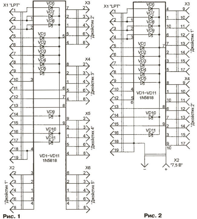
The cathodes of all previously existing and newly introduced diodes are connected in parallel. Thus, in the power of the joystick includes all port on which software is installed or can be installed level of the log. 1. Of course, the load is distributed unevenly between the lines, the percentage of the current gives TA, the voltage at which a little more than others. However, the possibility of simultaneous power five joysticks "Dendy" or two "PlayStation", the number of "DUAL SHOCK", is confirmed experimentally.
Diodes VD7, VD8 (see Fig. 1) or VD7-VD9 (Fig. 2) and perform additional function - protect the chip of the joystick from latch-up, not giving the voltage at its inputs to rise above the supply voltage by more than the percentage the direct voltage drop across the Schottky diode. This voltage never exceeds where may open a "normal" p-n junction in the device, can trigger latch-up.
Motivated by the socket LPT port of the computer to plug in both cases X1 adapter - DB-25M. Diodes VD1 - VD11 is placed inside the housing of the plug, solder them directly to the contacts and well isolating segments PVC pipe of suitable diameter.
The pin numbers of the connectors x2…X6 in Fig. 1 shows for plugs DB-9M, stacked narrow cable outlets joysticks. If you need to connect the joystick with "wide" socket, plug, DB-9M to replace DB-15M to reflect those in table of differences in pin assignments. As x2-X6 can be applied the plug on the failed video-game consoles.
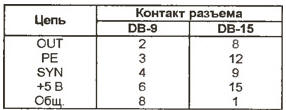
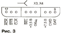
The last option is almost only for joysticks from "PlayStation", as suitable as XS and X4 socket (Fig. 3, a side view of sockets) can only be found defective in the video game console. If there was no need to use separate sockets required size, put on the appropriate pins cable plugs.
The length of the wires connecting the adapter to the electrical outlets (plugs) joysticks, not exceed 1 m. it is Better to use ribbon cable. If we restrict ourselves connecting one joystick connector may be mounted on the plug X1. And you can opt out of the connector, solder the wires of the cable joystick directly to the power plug X1 and conclusions diodes VD1 - VD11. Naturally, such a joystick can no longer be connected to the video game console.
To complete the work joysticks "DUAL SHOCK" with feedback is needed from external source file for connector x2 (see Fig. 2) voltage of 7.5 V, no required by the other types of joysticks. The source must be rated for a current of less than 0.5 A (for each joystick). It is recommended to increase the voltage to 9 In which drastically increases the recoil effect. However, the result is overheating the coil of the vibrator. No external power joystick "DUAL SHOCK" saves efficiency, but the volume is not valid.
As the diodes VD1 - VD11, in addition to these schemes, suitable or CDA other small Schottky diodes. In a pinch you can use ordinary CDB, but this will increase the possibility of unstable operation of some instances joysticks. All the diodes should be of the same type. Diodes VD6, VD9…VD11 (see Fig. 1) or VD6, VD10, VD11 (see Fig. 2) can not be installed if it does not to failures.
The relationship between the joysticks connected to LPT port of PC, and game the software package provides the DirectPad Pro. The package was developed by Earle F. Philhower III in 1999, its Included drivers work under Windows-9x, using a set of instructions Directlnput DirectX 5.0 and older. By installing a package DirectPad Pro on the new system game controller - joystick DPP".
Set DirectPad Pro in the following order. Creating a separate folder (for example, DPP) and unzip the archive into it dpadpr50.zip need acting on a "My computer" - "control Panel" - "Game controllers" - "Add" - "Add" - "Install from disk", to report the name of the folder operating the computer's system. In the displayed file list, specify the DirectPad Pro.inf, double-click PKI, select device DirectPad Pro Standard And Force FeedBack.
Next, scroll down the list of gaming devices DirectPad Pro Controller (joystick "Dendy" and "PlayStation") or DirectPad Pro Force FeedBack Controller (joystick "DUAL SHOCK"). Clicking "Properties", select the controller - NES for "Dendy" or one of five proposed by computer option (usually - PSX Digital or PSX Left Analog) for "PlayStation". It remains to specify identification number (ID) of the joystick (1 for the first set, ascending order of numbers to follow) and the address of the LPT port to which it will be connected. Find the address of the port on a "My computer" - "Panel management" -"System" - "Hardware" - "Ports COM and LPT".
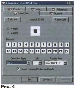
It remains to calibrate the joystick, pressing the buttons and watching tab "Configure" window "Properties" (Fig. 4) the movements of the black rectangle inside the white square. When it crashes it should be in the "Advanced" tab of the same window to increase the value of the PSX Scan Delay from 3 to 10. There you can pick up the parameters of the Sine, Ramp, Const, Spring for best effect return communication joystick "DUAL SHOCK".
In most programs that simulate the operation of the video game on the IBM PC, support joysticks DPP provided. To download free emulators video game console for example, from website <http://emu-russia.km.ru>. In principle, with the joystick DPP you can control the operation of any computer program. For this purpose there is several free emulators, for example, joyemu41 (author Simone Zanella). After any of them all of the operations previously performed by using the "mouse", you can use the joystick DPP.
Supplement
When you connect the joystick from a video game console Sega to LPT port under the scheme, recommended by the author of the package DPP, modern IBM-compatible computers, unlike their obsolete versions not respond to pressing the buttons UP/Z and DOWN/Y joystick. According to this scheme (in a file called genesis.gif) mentioned buttons connected to lines STROBE AUTOFEED and LPT port, which displays the digits 0 and 1 register printer. For the programmer it portan (LPT1) or AN (LPT2). Explanation of incompatibility could not find any Internet site. I had to carefully examine the device adapters LPT port personal computers of different generations.
In Fig. 1,and shows a typical diagram of input and output circuits of one of the discharge the control register of the "old" LPT adapter used in the IBM PC/XT, the clones and in some computers, later generations. With the pin of the connector directly connected to the output of open collector inverter DD1, loaded resistor R1. This is connected to the input of the inverter DD2. Standard use the register to output the control signals to the logical printer the level at the output of the element DD2 repeats an input element DD1, and the level at the contact of connector X1.1 inverse.
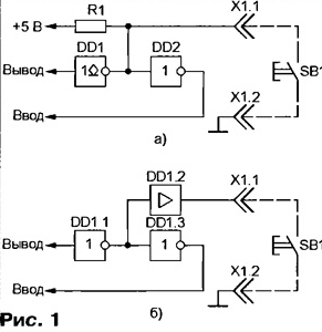
Software driver joystick Sega uses "forbidden". Record log. 0 in the corresponding position of the register control at the exit of the element DD1 installed high voltage level. In this state, the output transistor inverter DD1 is closed and does not affect the operation of the node. Connected to the contacts connector X1 joystick button SB1, when clicked, will connect the input of the inverter with DD2 common wire. As a result, the reading of the control register of the computer processor will give in the corresponding bit 0 release the button 1 is pressed.
In modern computers, input and output circuits of the control register is built on another scheme, shown in Fig. 1,6, and the elements DD1.1-DD1.3 are, as a rule, within BIS. Logic standard (output only) host remains the same, but the reception was not taking place. Therefore, the computer and does not respond to pressing the buttons UP/Z, DOWN/Y joystick.
Improved circuit connections of the joystick from a video game console "Sega" with the computer shown in Fig. 2. There are three differences from the original. First, the signal from the button DOWN/Y previously submitted for an available pin 15 (ERROR) plug X1. Secondly, the transistors VT1 and VT2, on base of which is filed with the signals from buttons UP/Z and T/X, and their collectors connected together and to pin 10 (ACKNLG) plug X1. The emitters of transistors respectively connected to contacts 1 (STROBE) and 14 (AUTOFEED) plug X1. Thirdly, the added diode VD8, reducing the probability of "thyristor" effect in a CMOS chip on the joystick.
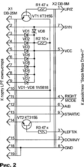
The position of the button DOWN/Y is now displayed in bit 3 of status register printer by address 379h for LPT1 or 279h for LPT2. In bit 6 of the same register depending on the voltage levels of the installed software on the emitters transistors displayed position of the button UP/Z or LEFT/X. for Example, if pin 1 low and pin 14 is high level, the transistor VT2 constantly closed, a VT1 opened high and closed low at the line UP/Z. When inversion levels at pins 1 and 14 is permanently closed, the transistor VT1, a VT2 is open at high and closed at a low level on the line LEFT/X.
Power to the joystick is supplied by VCC through the coupling diodes VD1-VD8 from eight lines LPT-port, seven of which (contacts 3-9 fork X1) high the logic level is present constantly. Current consumption depends on joystick the number of simultaneously pressed keys and does not exceed, as a rule, 2…4 mA. The voltage of the joystick does not exceed the limits of 3.5-3.8 V (VD1-VD8 - diodes the Schottky indicated in the figure) or 3.1 …3.4 In (ordinary silicon diodes).
All of the elements of the transition device can be placed inside a plastic the housing 25-pin plug to DB-25M (X1), pripaivaya their findings directly to contacts. Plug the DB-9M (x2) are connected with the rest of the flat deleteprogram ribbon cable or a bundle of insulated stranded conductors not less than 0.2 mm2 and a length of not more than 1.5 m.
Resistors - any small. The values of two of them (R1 and R3) and uncritical can be in the range from 22 to 82 ohms. The transistors KT315, CT, CT with any alphabetic indices or other low-power silicon structure n-p-p. You should not use the transistors with ultra-high (more than 250) value ratio, low gas consumpti yente h21e. Diodes with a barrier of a Schottky 1N5819 can be substituted KDA. If you install a typical silicon diodes, for example, CDB, reduced the voltage of the joystick, resulting in some instances can working with failures.
To adapt to a new way of connecting the joystick consoles Sega to files dpadpro.vxd and dpadpro.dll package DPP version 5.0 changes. The upgraded package (version number changed to 6.0) Packed in the archive dpadpr60.zip where in the folder With++ there is also the original text of the new routines polling the joystick.
When you install a new package on the computer, follow the guidance the above-mentioned article by choosing an appropriate stage of the process controller "Genesis" (joystick with buttons UP, DOWN, LEFT, RIGHT, A, b, C, START) or "Genesis 6 button (buttons added X, Y, Z, MODE). When working with joysticks from other video new version is no different from the original 5.0.
If during the calibration procedure detected a wrong reaction of the computer on clicking the buttons on the joystick, the reason is usually errors in the matching mounting device.
Package DPP is designed to work under Windows 9x. For operating systems Windows 2000/XP you will need an additional driver NTPAD XP.
The DPP software package version 6.0.
Author: S. Ryumik, Chernigov, Ukraine