


")

In apartments many people today have two or three TVs, and in some VCRs, and stereos with tuners This encourages УSW radio Amateurs (but not only) to create in apartments or private homes a small television network. Their essence consists in having one the MB antenna and UHF, or a single broadband antenna, to ensure the distribution of all the received signals on all consumers in different rooms apartment (several apartments) or at home. Naturally, the quality of the signal should to be good, regardless of the number of network-connected apparatuses and length coaxial cables.
About passive home network has previously been described in [1]. In low level signals from the antenna or with long cables to achieve good image quality on the TV screen in such a network is not always possible. So in this situation it is desirable to use broadband active splitters signals [2]. However, do not necessarily produce broadband transistor amplifier splitter. To amplify the signal quite you can use a plate and ready aerial amplifiers (PAHs), for example, series SWA, GPS, RYE, etc.
As noted in [3], with the exception of the input PAHs balun-matching transformer it has an input impedance of about 75 Ohms. This allows to include it in the gap of the coaxial cable or to connect to different the signal splitters. And when you consider the low cost of PAHs and wide range of different models with different gain, frequency response and noise characteristics, it is of interest to use in such amplifiers domestic (house) amplifiers in a cable television network apartment (several apartments) or at home.
Schematic diagram of the basic unit U1 of the network depicted in Fig. 1. In it includes the power supply unit-integrated stabilizer DA1 and network the transformer TK, two hybrid coupler on transformers and resistors Т1R2 and T2R3, and also a plate amplifier A1. Slot XW1 this block connect the cable from an active broadband antenna, for example, is widely known ASP 8WA (CX-8WA) [4-6], as well as similar imported or domestic.
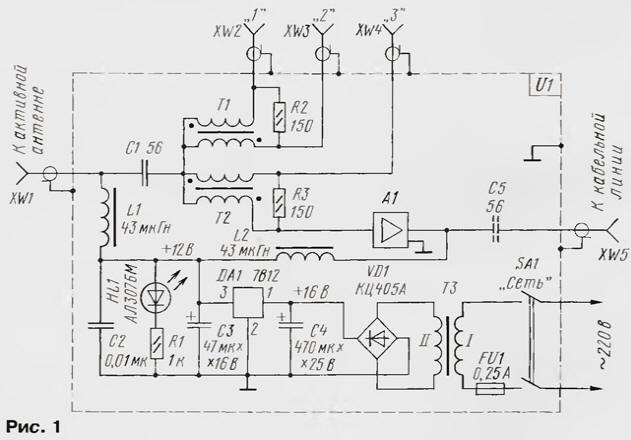
Adopted by the antenna and amplified built-in TV signal amplifier flows through the capacitor C1 on two hybrid coupler. With two outputs tap T1R2 signal through the slot and XW2 XW3 goes to the consumers for example, the TV and VCR. From one output of the coupler T2R3 the signal arrives at the nest XW4, which connect, for example, the tuner УSW the music center. The other output of the coupler signal input broadband plate of the amplifier A1 (PAHs). Again note that balun-matching transformer at the input to the amplifier is removed and the signal from the tap is fed directly to the coupling capacitor at this input [3].
The signal output from the amplifier is fed to the slot XW5. It connects the cable going to another room or apartment, where, if necessary, establish one of the blocks considered further.
The power supply base unit U1 consists of a mains transformer TK rectifier VD1, integral stabilizer DA1, two and one smoothing bypass capacitors C2 - C4. It forms stable voltage +12 V, used through decoupling inductor L1 and the antenna cable for power antenna amplifier, and through the inductor L2 to power the amplifier A1 main unit and amplifiers of other units (if fitted). The additional power is fed through a cable plugged in to the XW5. Led HL1 indicates the inclusion of the main unit to the network.
It should be borne in mind that if in a subsequent distribution blocks amplifiers not installed (applied passive splitters), the output unit U1 need to enable the coupling capacitor C5 (drawn dashed line).
The active block is further split signals may serve as the unit U2, schematic diagram of which is shown in Fig. 2.
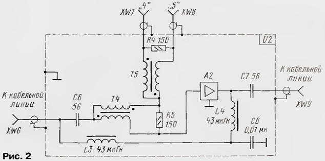
The signal from the main unit U1 via socket XW6 and the coupling capacitor C6 is supplied to the hybrid coupler Т4R5 in which it is divided into two areas: hybrid tap Т5R4 plate and the amplifier A2. With the two outputs of the coupler T5R4 the signal reaches the nest XW7 and XW8 for connection of the following consumer signal.
The amplifier A2 amplifies the signal to the level required for transmission cable through the slot XW9. Power to the amplifier A2 is supplied by cable from the unit U1 via an isolation circuit L3C8L4. If the output of U2 is planned to connect another active signal splitter, to ensure his power cable you must remove the capacitor C7 and the signal directly on the nest XW9. If you want to the active unit to connect the third consumer, the inclusion of hybrid couplers need to do as in block U1.
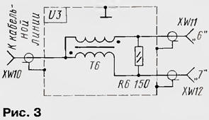
In Fig. 3 shows a schematic block diagram of a passive distribution signal U3 for the two users. It contains only one hybrid coupler Т6R6. This unit can be connected to the output of any of the above units U1 and U2 with sufficient signal level to them.
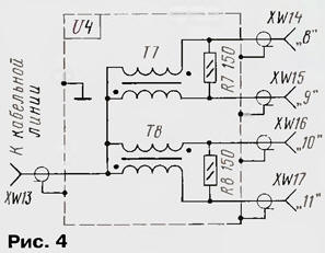
When a large signal level can to establish a passive unit U4 in four consumers. Its schematic diagram depicted in Fig. 4. It contains two hybrid coupler T7R7 and T8R8, distributes the signal to four directions through the slot XW14-XW17.
In all of the described blocks can use any capacitors and resistors. Led HL1 - any domestic or imported. Integral stabilizer DA1 - M, KREN, KEN, CREA, CREB. Anode bridge VD1 - any from the series KTS405, CC etc. Mains transformer TK - any capacity 3…5 W, having the output AC voltage of about 13…15 V at a current of 0,3…0,5 A.
It should be borne in mind that if the unit U1 is connected to the network around the clock for example, when using cable network into several apartments, then you need to use the transformer from the increased electrical safety, for example, TP-121-8, TP-121-9, TP-112-10, TP-112-11. Network switch SA1 - any, for example, PT-73.
The transformers T1, T2, T4-T8 hybrid couplers are the same. They wound double folded and twisted wire PEV-2 in diameter of 0.2…0.3 mm on the ring ferrite permeability 600…2000 and an outer diameter 7…10 mm. Winding contain 10 turns of wire, evenly spaced around the ring. When connecting transformers should observe correct phasing of the windings. The inductors L1-L4 - standard, for example, DM is 0.1, with an inductance of 25…45 µh.
As broadband amplifiers A1 and A2 can be applied, as stated above, PAH series SWA, RYE, GPS, RA, etc. the Information on them can be found in [4-6]. In [4], apart from the main parameters, are presented and their frequency response that will help you choose the amplifier depending on the gain in a particular frequency interval. It should be remembered that when a large transmission coefficient overloading and excitation of the amplifier. In addition, you must keep in mind that AFC PAHs pretty uneven, and in their consistent inclusion of the resulting frequency response of the tract is obtained by multiplying the frequency response of its constituent nodes and irregularity increases. Therefore, in the proposed units U1 and U2 is the best to use single-stage amplifiers, for example. SWA-1, SWA-1 LUX, PA-2, having a coefficient of gain 10…15 dB, or two-stage with a gain of 30 dB, for example, SWA-LUX 4, SWA-455 LUX, PA-10. PARADISE-14. WA-031,WA-032.
All the described units U1-U4 are mounted each in a suitable sized enclosure plastic or fiberglass screen and be sure. Details mount hinged manner. Conclusions the conclusions should have minimum length. Led HL1 and the switch SA1 of the unit U1 is placed on the front panel of the housing. Connect the blocks between themselves and with consumers coaxial cable with a characteristic 75 Ohm through standard plugs and jacks. However, it is better to apply special threaded cable connectors that do not require desoldering the cables and having high connection reliability.
Using the blocks in different combinations, you can make a small the network in order to connect multiple consumers of a signal located in different places to the same antenna without any noticeable deterioration of signal quality. The main condition for high-quality network - good signal with passive or active antenna (or multiple antennas), so in the first place, you should to pay attention to it.
Literature
Author: I. Patchin, Fokino Bryansk region.