


")

Broadband power amplifiers (NOISE) applied sverkhshirokopolosnykh the radar systems and communications, the construction of tunable lasers, creating a panorama measuring impedances and modulators of laser radiation. The proposed NOISE designed to work as part of the system cable TV, providing local broadcast 5…10 TV channels broadcasting in low-lying residential areas. This amplifier is a modification of amplifiers described in J1]. Its advantages include ease of fabrication and settings, high gain, manual gain control and indicator output power level.
The amplifier (Fig.1) contains five stages gain on the transistors VT2, VT4, VT6, VT8, VT10.
(click to enlarge)
All the amplifier stages operate in class A with a fixed working point and the quiescent currents of transistors VT2, VT4, VT6. VT8, VT10, equal to 0.08; 0,12; 0.3; 0.4 and 0.4 respectively. Stabilization of the quiescent currents of the cascades is achieved thanks to the application schema active collector thermal stabilization [1, 2]. Choose the quiescent currents in this case are set by selection of resistor R6. R11. R16, R21. R26. The decrease in the resistance of these resistors reduces quiescent currents, and Vice versa.
In all stages of the amplifier, in addition to output, used jet interstage correction circuit of the third order [1, 3], where as a of the elements of the correction circuit uses the reactive component of the input the impedance of the transistor [4]. The output stage is executed according to the scheme with addition stress and performs summation in the load signal voltages, produced by transistors VT8 and VT10 [1.5]. When assembling the amplifier should to minimize the length of the chain connecting the collector VT8 with the emitter VT10. It due to the fact that the presence of an inductive component in this circuit leads an incomplete summation of signal voltages produced by transistors.
The power amp circuit Board (Fig.2) size 180x80 mm made from bilateral foiled fiberglass thickness 2…2.5 mm Location items on the Board of the MIND shown in Fig.3.
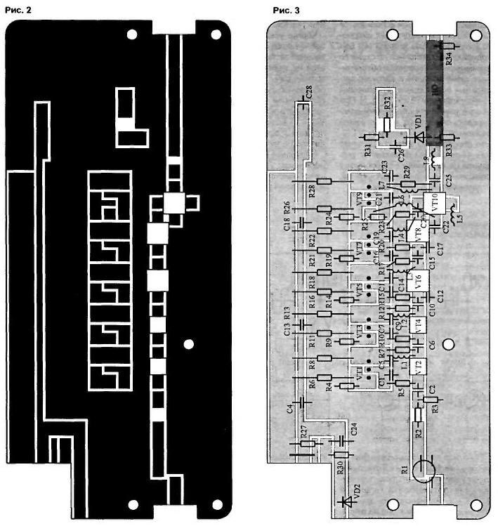
(click to enlarge)
Dashed lines indicate locations metallization of the ends. Metallization is needed to eliminate spurious resonances and grounding the desired areas of the PCB.
The amplifier used a non-inductive type capacitors K10-42 in the high frequency path and type K10-IC-29b filtering circuits.
The body of the amplifier (Fig.4 and 5) is made of duralumin and long-term exploitation is mounted on a small heatsink. All transistors of the amplifier attached to the base provided with heat-conductive paste. To improve thermal contact with the transistors VT2 and VT4 from the amplifier they are pressed to the glass fibre laminate base plate (Fig.4).
Tuning the amplifier consists of several stages. First, with the help of resistors R6, R11. R16, R21, R26 set the quiescent currents of transistors VT2. VT4, VT6. VT8, VT10 DPJ that, these resistors are alternately replaced with potentiometers, measured the voltage across the resistor R8, R13. R18, R22, R28 and defined the required quiescent currents of transistors VT2, VT4, VT6, VT8. VT10. Soldered all elements of high-frequency path with the exception of the capacitors C12, C17 and C22.
Note. Capacitors CC, C8 and C in Fig.3 are not shown, their role metallized areas, to which are soldered the base of transistor VT2, VT4, and the PCB track leading to the output NOISE.
When you turn on the amplifier without the capacitors C12, C17 and C22 its frequency response in small the uniform signal frequencies up to 400…500 MHz with a further slow decline, components at the frequency of 800 MHz to about 4,..7 dB. Connecting the capacitors C12, C17 flattens out the frequency response in the frequency range 500…800 MHz.
Moving from small signal to the restriction mode (output stages), with through selection of the capacitance C22 achieve maximum power output the amplifier in the frequency range.
The output capacitance of the transistor VT10 is connected in parallel with the load, that reduces the maximum output power of the amplifier as the frequency grows. To address this deficiency at the output of the amplifier is installed elements 18 and S, forming together with an output capacity of VT10 filter bottom frequencies [1]. Therefore, by varying in a small range of inductance L8 achieve alignment of maximum output power of the amplifier in working frequency range. And finally, selecting the quiescent currents of transistors, need to find the values of currents at which the amplifier gives the load the required power at minimum power consumption. Manual adjustment the gain realized on the potentiometer R1 and provides depth control 12 dB in the range of 400…800 MHz with a gradual increased level of regulation to 30 dB lower signal frequencies up to 45 MHz.
For indication of the output power of the amplifier at its output installed directional coupler (BUT) incident wave. Directional coupler made in the form of a piece of fiberglass with a length of about 4 cm with double-sided metallization, placed over the strip long lines going to the output of the amplifier. Together with detector diode VD1 and a needle indicator type M4761-M1 directed the coupler allows you to control the output power level in working the frequency range with an accuracy of 4..C. 5 dB.
Literature
Author: A. Titov, Tomsk