


")

Reception of signals of satellite television has become commonplace in the press often discuss issues of STV, constantly publishing program the different channels. But with a sound broadcasting via the same satellite perhaps not all familiar. Meanwhile it is not less interesting than television. For lovers of home libraries are another source of replenishment of their collections.
You probably know that satellite television is not only, but also broadcasting, including stereo. Provided it is in sound subcarriers located above the bearing of the sound image, in between 7 and 8.5 MHz. This service is available for many popular channels series satellites "MUSIC ВIRD" (13 ° e), as well as others, including "gals", where these transmissions are not yet coded. Naturally, these programs are capable of take modern receivers, including NTV-2000" and "NTV-1000".
However, they only have linear outputs, and accept to play audio programs (without the TV), you need a power amplifier and the speaker system. There is no problem if the receiver together with a TV is near or at least in the same room with existing audio complex. Then it is only necessary to connect the audio outputs of your receiver to the inputs complex. If this is not possible, then to listen to the will turn on the TV and use it as amplifier and acoustic system.
The last of these options is unlikely to be considered rational. To solve the problem can different installation in the housing of the receiver USC and dynamic heads, there for it is quite enough. When such a simple rework of the receiver turns into a radio. Of sound quality this is not particularly great, but it is nowhere near the sound quality of portable, small, and especially handheld radios УSW FM.
Undoubted advantage of "satellite radio" - its consumer features: using the receiver's remote, you can switch programs, to adjust the volume, mute the sound (MUТЕ") and off by the receiver. Proposed revision provides for the mode on and off audio internal dynamic head .
Diagram of the device that turns the receiver in the radio receiver shown in Fig. 1. The heart of this device the amplifier of sound frequency (USC) on the chip CAN (you can use its foreign counterpart TDА2003). The amplifier circuit in mostly standard, but it additionally introduced the VT1 transistor, and to switch the receiver mode to "stereo."
It happens this way. The input USC through resistor regulator volume R1, resistor R2 and capacitor C1 with the line audio output of the receiver goes beep. If the transistor is closed (voltage control, entering the pin 3, is equal to zero), the signal CC comes to the input circuit and she works in a usual mode. When submitting same to the output 3 voltage 5…12 In the transistor opens, the signal CC is shorted to a common bus mode and at the same time chip DC voltage will change its output transistors is closed, i.e. it comes out of reinforcement mode. This allows, first, to exclude different kinds of acoustic noise and switching noise, and, secondly, in this mode decreases current consumption of the chip (10…15 mA).
To switch the modes of the receiver is convenient to use the command "/ku". It due to the fact that most of the satellite TV programs posted in Ku-band (10.7 per…12,75 GHz) and C-band (3.7 V…4.2 GHz) is used infrequently. When you switch to the mode "C" inversion of polarity of the output video signal receiver, so you can watch it on the television screen impossible, but in this case, this is not required. The control signal can be removed from the output resistor R711 (near to the jumper J26). In this output mode "ku" voltage of 12 V, and in the "With" it is not (or significantly less than threshold opening of the transistor).
In your device, you can use the following components: transistor with KT3102 alphabetical index A through E, CTW; polar capacitors - C50-24, nonpolar - km, KLS. Trimmer - SDR, constant - MLT, S2-33. All parts of the device, in addition to the dynamic head, placed on a printed circuit Board from one-sided foil fiberglass (Fig. 2).
Cost install the side wall of the receiver for a power transformer (Fig. 3). The chip to the Board solder marks to the Board and is attached by a screw-a screw to a ledge in the side the wall - as providing the mounting Board and at the same time from the heat sink chip.
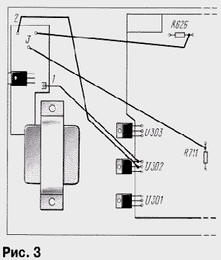
Charge to the receiver plug: pin 1 is the output circuits of the stabilizer U302, pin 2 to GND power on the chip U302), pin 3 - the resistor R711, pin 4 to the output resistor R626 (near to the SCART connector).
Dynamic head should have a resistance of 6…8 Ohms and a capacity of 0.5…1 watt.
The establishment is reduced to the maximum volume setting resistor R1. Program the receiver for broadcast reception as well as reception TV when tuned to one of the programs. But after tuning to the desired sound subcarrier set the range "C" and the data are entered into the memory receiver.
Author: I. Nechaev, Kursk