The switching power supply is one of the nodes of imported TV sets, which often just fails. Concepts, usually absent. In published article the power source of several models of foreign TVs and make recommendations for its repair. I think the advice of the author will be useful to Amateur radio operators and employees of the maintenance of telemasters.
Lately when repairing TVs, cases of malfunction switching power supplies are mainly collected on four transistors (in the primary circuit). These blocks differ little from each other, often - types of used semiconductor devices (characteristics they are similar and interchangeable). Absolutely like the power supplies found in TVs PHILIPS - 2021, AKAI - CT-1407, AKAI - 2107, SHERION, CROWN - HUNDRED/ 5176, ELEKTA - CTR-1498EMK.
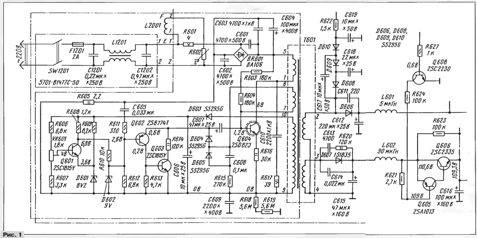
Consider the following source used in the CROWN TV - CTV5176, schematic diagram of the unit shown in Fig. 1. The voltage is 220 through filter the power supplied to rectifier BR601, S - S and loop demagnetization L2001. The key collector of transistor Q604 rectified the voltage passes through the coil 1-5 pulse transformer T.

(click to enlarge)
Transistor Q604 made the blocking oscillator - voltage positive feedback is removed from the windings 7 and 8 of the transformer. Duration generated by the blocking pulse generator, i.e. the residence time of the transistor Q604 in a saturated condition, is determined by the operation of the pulse width modulator (PWM).
To the base of transistor Q604 connected capacitor C that during the closed the state of the transistor is charged by a pulse voltage winding 7 - 8 transformer through the diode D604. When the lid of the transistors Q602, Q603 PWM capacitor C is connected to the emitter saturated transition transistor Q604, and the discharge current of the capacitor flowing through the transistors and resistor R616 quickly closes the transistor Q604. The bias voltage to the base transistor Q604 is fed through resistors R603, R604. The circuit limits C610R617 the emission of pulses at the collector of transistor Q604, protecting it from breakdown.
To power the DC amplifier transistor Q601 AC voltage with the windings 9 and 10 is rectified by a diode D603 and charges the capacitor C.Voltage the emitter of transistor Q601 stable parametric stabilizer the elements D601, R609, and the voltage at the base of the transistor is removed from measuring resistive divider R606VR601R607. The latter depends on the voltage across the winding 9 - 10 transformer, i.e. the levels of output voltages power supply + 110 and +12 V. the voltage across the resistor R608 - collector the load transistor Q601 is the error voltage and controls the moment opening the PWM transistors Q602, Q603. A trimming resistor VR601 set output voltage + 110 V.
With resistor R605 through the chain C605R611 removed the sawtooth voltage at the base transistor A shaper PWM. It comes an error voltage with the collector of transistor Q601. Depending on the last PWM opens earlier or later, counting from the moment of opening of the transistor Q604. Transistors Q602, Q603 represent the analogue of the SCR. Its principle of operation is similar to operation the SCR pulse in the power module MPZ-3.
By increasing the voltage or reducing the load increases the voltage on the winding 9 - 10 transformer T. As a result, the transistors Q602, Q603 open earlier, closing at an earlier time the output transistor Q604. The reduces accumulated in the transformer T energy that compensates the increase of voltage.
By lowering the voltage will lower the voltage across winding 9 - 10 transformer T. The collector of the transistor Q601 voltage error decreases, the PWM is opened at a later time, and the amount of energy transmitted to the secondary circuit increases, compensating for the decrease in voltage network.
The secondary rectifier unit is based on half-wave circuit. Coil 4 - 2 transformer and elements D606, S, L601 form a source voltage of +12 V, used for system control and other low voltage circuits. Coil 4 - 3 and elements D607, L602 enter the source voltage of +110 To feeding the output the cascade horizontal.
Transistors Q608, Q606, Q605 assembled the node on and off power output stage line scan. The TV system remote control included or off, i.e. operational or standby mode. In standby mode transistor Q606 is closed and the voltage of +110 is not supplied to the output the cascade horizontal. Some TV models for this purpose applied relay.
Typical failures of this power supply are similar to the fault module MP3-3. For the repair cost of the unit is removed from the housing of the TV and post it so that was the free access to the elements. Parallel to the capacitor C connect a resistor of 220 ohms and a power dissipation of 0.5 watts. Through it will discharge the capacitor after turning off the TV. Fed one from the conclusions of each of the elements L601, L602, D608, S. Thus the load circuit the TV will be completely disconnected from the power supply. Parallel to the capacitor S connect an incandescent lamp at 220 V and 25 W, which will serve as the equivalent load of the power supply.
After repair, before connecting the power supply to the circuits in the TV, be sure you need to check the output transistor horizontal and the secondary circuit the flyback transformer. With the secondary winding of the latter is often taken the voltage is rectified and smoothed to power the nodes of the TV. One of causes of failure of the power supply unit can be exactly these chains.
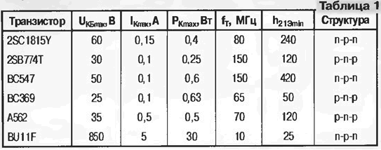
In the selection transistors to replace the failed one should be guided by their characteristics, are listed in table. 1.

2SC1815Y transistors can be replaced by CTB, 2SB774T - CTB, a 2SD820, BU11F - CTA. The latter are fixed on the heat sink with an insulating gasket. Diodes permissible to replace CDB, CDA, CDB.
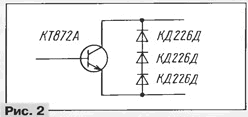
The output transistors horizontal 2SD2333, 2SD1876, 2SD1877, and 2SD1554 other, having a built-in damper diode, replace CTA by the circuit of Fig. 2. Attach it to the heat sink via an insulating gasket. You can use transistors CTV, KT838A, however, will have difficulties in their attachment to to the heatsink.

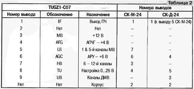
When failure of the channel selector import TV can be replaced by selectors SC-M-24 and SC-D-24. Compliance of their findings, for example, conclusions selector TUGZ1-C07 shown in table. 2.

Letter designations of the findings of the selector are on pay TV, and rooms conclusions on the case selector. Within the TV national selectors is fixed by any method, and output antenna Jack on the TV. All connectivity (wired), make, possible, short conductors.
In the extreme case when it is impossible to repair a switching power supply import TV you can recommend to replace it with domestic MSY-3, MP-42 etc. or Perhaps the unit is fully suitable for replacement, depending on the brand import TV. If output voltage does not correspond to used in TV, you have to switch the secondary winding of the pulse transformer and how to adjust the springs for the relevant TV voltage. The unit when adjusting the load of an incandescent lamp of 40 W and 220 V, are connected to the winding voltage of 130...150 V.
It should be remembered that the windings at no-load idle will be a little too high a voltage. Unused winding leave unconnected. Not forget to connect the loop degaussing.
The switching power supply is placed in an open space inside the TV and reliably fix.
Author: B. Kiselevich, p. Khatanga, Krasnoyarsk Krai


