


")

Many owners of radio equipment I prefer to use only "branded" appliances. However, it should be remembered that "brand" is not always universal. This includes playing video game "PlayStation", brought from foreign countries. They often refuse to work with laser discs purchased abroad, and especially at the local the market. The author proposed article discussed some of the ways to overcome this problem, here he continues this theme.
Sony produces only localized versions "PlayStation". Each of them is designed for television and other standards used in a particular region, and is intended for use only there. Main the parameters by which these variants differ, are shown in table. 1. To adapt the "American" or "Japanese" console connected to the mains power supply 220 V 50 Hz. it helps to have a step-down transformer. It turns out that the problem of disparity between TV standards to solve is quite simple.
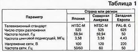
Television standard are designed to have acquired the set-top box, can be defined not only by the inscription "PAL" or "NTSC" on the label to the bottom of the shell, but the last digit in the model number: console SCPH-xxx1 - "U.S.", SCPH-xxx2 - "European". In difficult cases, the answer will frequency of crystal oscillator H on the CPU Board [1]: 53.2 MHz - PAL. 53,69 MHz - NTSC.
Standard game programs is usually printed on the cover of the case disk. Indirectly about it says "geography" of the firm whose name appears on the TV screen while loading the game: "Sony Computer Entertainment Europe" produces games in standard PAL. a "Sony Computer Entertainment America" - NTSC. To accurately determine standard can the human clock frequency generated in the console the video signal. For PAL it is $ 50 for NTSC - slightly less than 60 Hz. Drives both standards are found in the markets of the CIS countries quite often. Moreover, "craftsmen" working Russification programs, manage to write one laser disc games in different television standards.
Branded top box work fine only with discs"" standard. If there is a mismatch (for example, console PAL disc to NTSC, or Vice versa) the game program can't start, but the image on the screen of the TV color and black and white Connect the top box to the most modern TV with decoder, automatically determining a method of transmitting signals chromaticity, in this situation does not help. To understand the cause of this phenomenon, consider a used in "PlayStation" ways to control the formation of television signal.
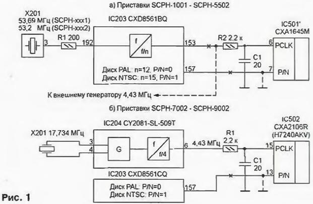
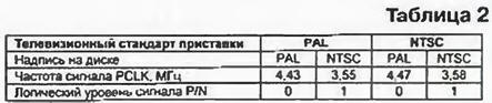
The schema fragment produced until mid-1998, the video SCPH-1001, SCPM-5501. SCPH-5502 shown in Fig. 1,and. In the RGB encoder-PAL/NTSC (chip IC501' SHAM) graphics coprocessor (chip IC203 CXD8561BQ) the signals P/N and PCLK. The logic level of the first one sets the standard the generated video signal, the second frequency equal to the frequency of the color subcarrier. In graphics coprocessor signal PCLK obtained by dividing the frequency of the clock signal GCLK. coming from the crystal oscillator H. As mentioned above, the frequency GCLK equal to 53.2 MHz in the "European" and 53.69 MHz in the "American" versions console. Regardless of the standard top box graphics coprocessor sets the division ratio n and the logical level of the signal P/N. analyzing data included in the games program.
All possible combinations are shown in table. 2. It is easy to see that the mismatch of standards leads to the formation of television signals with incorrect values of the frequency of the color subcarrier. Decoders TVs, not finding the desired subcarrier frequency, does not include the channel color and the image remains black and white.
In later models "PlayStation" (SCPH-7002. SCPH-7502. SCPH-9002) management of the standard form of a television signal according to the scheme it is shown in Fig. 1,b.
For receiving the clock signals applied to the generator programmable frequencies (chip IC204 CY2081-SL-509T company Cypress Semiconductor). It contains three independent channels frequency synthesizer, and the output of each frequency can be both above and below, exemplary, asked a quartz resonator H. The factors of division or multiplication written in an internal ROM chip IC204, programmable the factory, and you cannot change them. As a result, the frequency of the signal PCLK is not rebuilt and is always equal to 4.43 MHz. The signal selection standard P/N as first, generates a graphics co-processor (chip CXD8561 any modifications). His logic level dependent on the information read from laser disk. The output of the encoder (IC IC502 CXA2106R or H7240AKV) formed television signal with the color subcarrier frequency of 4.43 MHz, modulated according to the standard PAL or NTSC. This is enough to get color image on the TV with multi-standard decoder. If the reception of signals in NTSC TV is not provided, the image when working with the drive of such a standard will be black and white.
To ensure obtaining a color image, the top box should always to generate PAL video signal it is enough to connect with General wire input P/N encoder, unplugging its eponymous graphic output the coprocessor. In consoles, the old issues still need to apply to the input PCLK the encoder clock signal standard PAL frequency of 4.43 MHz. These improvements it is shown in Fig. 1, a and b crosses (breaks conductors) and a dashed line. Although when working with disks NTSC field frequency of the image will remain equal to 60, and not 50 Hz, system frame synchronization of the vast majority of TVs with that it can handle.
The problem arises, where to get signal PCLK frequency of 4.43 MHz. If in the console installed the power adaptation [2], from him on the encoder and fed that signal. In otherwise you'll need to create it separately. In the presence of small quartz resonator frequency 4,433619 collect MHz generator transistor (his scheme shown in Fig. 2) or TTL logic elements (scheme in Fig. 3).
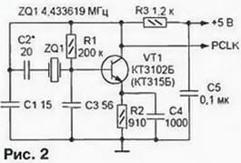
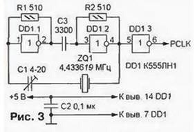
Selection or adjustment of the capacitor included in series with the resonator ZQ1. set the exact value of the frequency maximum stability of the color image. Tuning is quite sharp. For example, when establishing a transistor version of the image generator became black and white when the capacitance of the capacitor C2 is less than 10 and more than 24 pF.
If you need a quartz resonator not, can be divided into 12 frequency GCLK 53.2 MHz. Scheme of divisors on chips series KR1533 shown in Fig. 4,b. They vary the duty cycle of the output pulses. As check has shown, the encoder RGB to PAL/NTSC video game console is stable with any of them. It is only necessary, the magnitude of the signal PCLK were in the range of 0,3…5 V. Low-impedance matching the resistor R1 at the input of the divider, reducing the reflection of high-frequency components signal, eliminate "ringing" on the fronts of the pulses. In many cases, the input can to connect with the signal source without a resistor.
Counters series KR1533 at frequencies close to the limit, has some features. For example, in the first stage of the frequency divider is unacceptable ask the conversion factor, feeding the output signals to the reset input R. For short the period of the input signal triggers the counter will not have time to return to the source state. In the chip CREE cascade with the input of C1 - faster. If the signal frequency of 53.2 MHz to submit to the input of C2, and then use the input C1, the division may be unstable. For these reasons, in the first two variants the divider had to use two instead of one chip, as in the third embodiment, the frequency of the signal GCLK is first divided into four, and then three (but not Vice versa).
I conclude with some practical recommendations for the revision of the consoles. Usually need circuit break, carefully carving out small areas of the printed conductors. In the first models of the "PlayStation" instead, you can unsolder from pads and lift the pins 6 and 7 of chip encoder SHAM. and then submit them right from the thin wires (see Fig. 1, a). Resistor R2 is allowed to replace the bridge, and the capacitor C1 is to remove. Categorically not it is recommended to try soldering a thin conclusions graphics coprocessor IC203 or encoder IC502 (see Fig. 1, b). This. as a rule, leads to breakage of the findings or it may be more difficult flowing of solder on adjacent pads.
Oscillators or frequency dividers are harvested on small circuit boards dimensions approximately 30x40 mm. is Desirable to use one-sided foil fibreglass and arrange all the details from the foil without making holes under the conclusions. Such a fee is glued to the reverse side of processor Board "PlayStation" and combined with chip encoder and power supply circuits conductors length 120 mm.
An alternative is to mount the chip divider or generator for the conclusions pripaivaya them directly to the pads of the processor Board on served or from which appropriate signals are removed. Rest mounting - hinged. The processor Board must be protected from short circuits by using the insulating strip from the adhesive tape. Another original way is to cut additional contact pads on the CPU Board printed conductors of large area, for example, from the common bus wire. This will give design the necessary rigidity.
The gap between the housing top box and the processor card, which should fit the accessory, small. So choose all the details small-sized. Resistors - ALT-0.125. S2-23-0.062, capacitors - km-56, CT-25. CT-27. Trimmer capacitor C1 in the oscillator circuit shown in Fig. 3, it is permissible to replace the constant picking up its capacity. The capacitor C3 in many cases is not needed and is replaced by a jumper. Quartz resonator ZQ1 - RCM-VM-2 or suitable imported. Transistor VT1 - any low-power high frequency structure n-p-n. As the inverter DD 1.1-DD1.3 in the generator according to the scheme shown in Fig. 3. work elements AND-NOT, OR NOT any TTL chips, if the inputs of each of them to connect together. In the divider according to the scheme depicted in Fig. 5, the chip DD2 can be CIA or CIA.
All of the feed device available on the CPU Board "PlayStation" voltage of +5 V. the Right circuit easy to find, focusing on three-terminal integrated regulator TA78M05F (IC601). The current consumed the dividers. - not more than 30 mA. and generators - several times less. A blocking capacitor of 0.1 μf is set in close close to the power pins and the common wire chip oscillator or divider. If the length of wiring exceeds 50 mm, the capacitor is not mandatory.
Literature
Author: S. Ryumik, Chernigov, Ukraine