


")

A videogame console "Sony PlayStation" in the first place - a wonderful toy for of the younger generation. However, having connected to its connector PARALLEL I/O" additional MOVIE CARD or, otherwise, video-CD module (VCDM). you can still watch movies recorded on laser disks formats VCD 1.0. VCD 1.1, VCD2.0 (MPEG-1). The image is much better (without slowdowns and on the big screen), than when viewed with IBM-compatible computer, equipped with software An MPEG decoder. Convenient OSD menu, where items chosen by using the gaming joystick allows you to slow down, accelerate or stop playback, rewind the film in both directions, set the timer. Quality digital videos on laser disks, unlike analogue to VHS does not deteriorate over time, compact discs and cassettes less susceptible to physical wear. On one disc is placed not more than 74 min live video, so full-length movies recorded, usually on two, 45 min each.
Module VCDM the kit '"PlayStation" is not included, buy separately. Structural diagram VCDM is shown in Fig. 1.
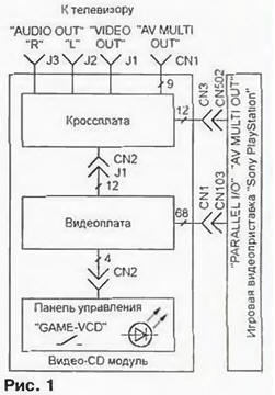
The outlet module is designed for connection with the top box, are arranged so that the joint-free cables plugs directly CN502 "AV MULTI OUT" and CN103 "PARALLEL I/O" Manufacturers carefully observe the size, so connection problems are not happen. The TV is disconnected from the top box and connect with deletecontact socket "AV MULTI OUT" of the module or of the same nest "AUDIO OUT FT", "AUDIO OUT L", "VIDEO OUT".
Intelligence VCDM is concentrated within the video card connected to the control panel and the cross-Board. The control panel has a switch mode.
When the contacts are closed ("VCD"). watch the video, and when open ("GAME"), working with the usual game drives. Built-in key switch the LEDs after you turn on view mode VCD burning constantly, and during the reading of information from video flashes with a frequency of 1 Hz. In game mode the led is off.
Through cross-charge at VCDM receives a supply voltage. It also serves for switching video and audio signals supplied to the TV. As this fee fully maintainable even at home, we begin the consideration circuitry VCDM.
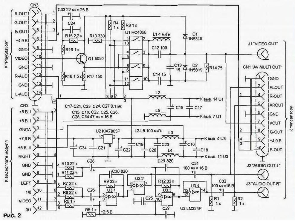
The cross-tab shown in Fig. 2.
(click to enlarge)
It is conditionally possible to allocate three channels: video (Q1, U1), audio (U3). power (U2). In the video channel backplanes full color TV signal amplitude of about 1.5 V from the "PlayStation" via materny the follower transistor 01 8050 (analog - CTB) is supplied to the switch - the chip U1 NS. consisting of four bi-directional CMOS keys managed the logic levels at the inputs 5. 6. 12. 13 To reduce the transition resistance of the keys of the switch connected in pairs in parallel. Full analogue chips NS - CTS.
Control the switch via signals "1/0" and "0/1". coming from the video card via the plug CN2. When a logical 1 of the pins 5 and 6 of U1 on the output signal is formed by "PlayStation", when a logical 1 on the findings 12 and 13 - card module. Through the filter (elements of L1. C12-C14) output the switch is connected to connectors J1 and CN1. designed to connect TV video input. Diodes D1 and D2, resistor R14 - matching.
In the audio channel of the audio signals produced by the "PlayStation" and the video card, are summarized. First go through the resistors R8 and R11. second through R7 and R10. Elements Quad operational amplifier LM324P (analog CRUD) U3.1 and U3.3 amplify the signals of the left and right stereo channels on voltage, a U3.2 and U3.4 - buffer. Capacitors C and C30. suppressing harmonics the frequency quantization of audio signals, reduce the "metallic" overtones. The resistive divider R5R6 provides a DC offset of 2.5 V to the non-inverting inputs of the opamps U3.1 and U3.2. necessary for normal operation last. Capacitors C25 and C - locking.
In the channel of the power supply voltage +V. 7.6 coming from "PlayStation", get +5 V. For this is the integrated stabilizer U2 KIA7805P (analog CREA). In a circuit has a large number of capacitors and chokes that suppress noise and parasitic coupling between video and audio channels. The current consumed VCDM, reaches 0.3…0.4 A. therefore, the regulator U2 is provided with a heat sink area of 40 cm2. The names of the circuits of the plug CN3 are as quoted in [1], socket CN1, CN2 - the marking on the PCB. Type of socket CN1 from the nests shown in Fig. 3. Such is installed in the video game console Sega Mega Drive-2". and with similar location and pin assignments 4, 5, 7-10.
Socket CN2 on the design is unique and applies only to "PlayStation". Its location nests are shown in Fig. 4.
Literature
Author: S. Ryumik, Chernigov, Ukraine