Games video game console "Sony PlayStation" popular all over the world. Those most often have to deal with in Russia and other CIS countries, usually have blocks of adaptation (sellers often call them "chip wagon", "chip-decoder" or simply "chip"). They equip the top box before the sale in the countries from which they come to us to sell. The author shares with readers the secrets of this block, which he managed to solve, and experience repair.
An adaptation block [1] need for "Sony PlayStation" with CD's South Asian production and also contains the Russian version game programs. Companies involved in the adaptation, in no hurry to part with know-how, bringing them considerable income. But nevertheless, if the block adaptation fails (and such cases are known), it is possible to repair it and can on their own.
There are several generations of these video game: "ones" SCPH - HHH (1995). "three" SCPH-Shhh (1996), "five" SCPH-5xxx (1997). "seven" SCPH-7xxx (1998) I. finally, "nine" SCPH-9xxx (1999). As increasing model numbers improve her energy, technology, reliability and economic performance while maintaining software and hardware compatibility.
In Fig. 1, a-d shows the typical block diagram of the adaptation of different video attachments. Positional notation chips missing on the printed the Board, designated by an apostrophe. Striking nepovtorimosti connection points blocks to the processor boards and a variety of types of chips. As chip SG used mainly by the eight-bit microcontrollers with internal ROM part no pic12c508/P. part no pic16c54a-041I/P from Microchip Technology, Z86E0208PSC firm Zilog or their frameless counterparts. Last after installation on the Board is filled with a drop of resin. A rigid connection between the microcontroller and model "PlayStation" does not exist. For example, in consoles SCPH-5502 can to meet and PIC, and Z86, and chip controllers. Blocks some adaptation models of consoles may not be appropriate for others (compare the scheme in Fig. 1, a, b, d).
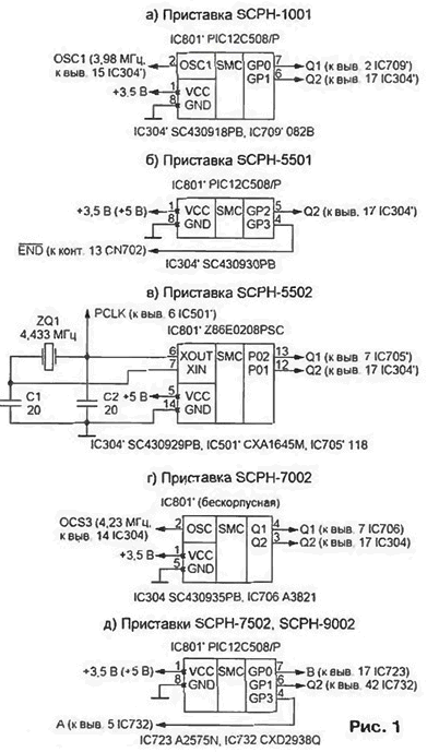
When embarking on the study of the adaptation block by the method described in [2]. before just need to determine which pins of the chip IC801 serves as the entrance, and some output. It is unknown in advance, as specified by the program located in the internal ROM of the microcontroller. To establish the truth, should to study the waveforms of all signals, alternately otaiba conclusions from the contact sites. The measurements were correct (if the output pin is open drain), sealed lead should be connect to a power source through a resistor of 100 kOhm. Another common trick is to check the response on pressing the "RESET" games console. The signal on the reset does not react with high probability - output, and Vice versa
As a result, it was found that the device, the schema of which is shown in Fig. 1, and. p have the same input clock frequency (3,98 4,23 or MHz) and two outputs. In the block diagram Fig. 1, the clock frequency of 4.433 MHz quartz resonator sets ZQ1. The output signal PCLK synchronizes the encoder RGB-PAL IC501. Device, scheme which is shown in Fig. 1. d, contains two independent channels: the first with input A and output B. the second - only with the release of Q2. This channel has no external log. Its operation synchronizes the internal clock RC-generators-tor microcontroller ST. In the device according to the scheme shown in Fig. 1. b. the signal Q2 is also synchronized internal RC oscillator. The input END signal is received from the mechanical switch located in the CD-ROM drive. Under its influence the adaptation unit re-generates the signal 02 every time. when the carriage actuator reaches the beginning of the information track laser disk.
To determine the moments when "PlayStation" perceive signals of the block adaptation will be during the download and execution of game programs temporarily disable its outputs Q1 and 02 from the CPU Board. It turns out that during the game the adaptation block is not needed! It is required only during the first 10... 12 after pressing the "RESET" button. During this time the operating system "PlayStation" double-checks the "brand" of the disk: the first time - before appearing on screen TV logo (a stylized sign of PS in the form of "Cobra" on a black background), second - before his disappearance and migration to the download of the game software. If in these moments, the signal Q2 is absent, a videogame console freezes, and the screen the TV appears the same inscription, and when you try to work with the disk from IBM PC: "Please insert PlayStation CD-ROM". A similar check is performed after each opening and closing of the access cover CD. Most likely, it is made for exceptions are situations when the game start with "brand", and continue with frills disk.
The logical rules in the signal blocks of adaptation will start with channel A - In the device, the diagram of which is shown in Fig. 1. D. using two-beam oscilloscope it is easy to verify that In - inverted copy of the signal A, and logic 1 corresponds to a high-impedance output state. Equivalent diagram of the channel - power inverter with open-drain (collector).
The logic level of the signal Q1. provided in the devices of the circuits Fig. 1. and. V, g, is set high immediately after power press "POWER" and remains so for a period of 0.1... 1.2 in accordance with the variants of the program of the microcontroller IC801. The rest of the time signal Q1 has a low logic level, in response to pressing the "RESET" button. On output 01 sometimes you can see two or three short (with a duration of tens microseconds) high level pulse before or after the main, but they are not affect the operation of the top box. The signal Q1 can be represented in the form of the waiting multivibrator, generating single pulse when the supply voltage is next applied. Of course, in real devices no multivibrator no. The signal Q1 form programmatically, counting necessary the number of pulses of clock frequency. In many cases, "PlayStation" normal without this signal.
The most complicated situation is observed for the signal Q2. It generate all without exceptions blocks of adaptation. Obviously, it contains code that allows loading programs from disk. The task that remains to be addressed is clarifying the law of alternation of low (logic 0) and high (logical 1) levels. Conventional oscilloscope't help here, as its sweep it is almost impossible to synchronize with the signal, consisting of a large number pulses of variable duration. However, the waveform can be seen that the pulse duration of both high and low level in all models "PlayStation" is close to 4 MS or a multiple of this value. A more detailed analysis possible by using a storage oscilloscope with large amounts of memory (S9-27. C9-28 or HP54C45D of Hewlett Packard). But ordinary Amateurs such devices, such as complex logic analyzers long pulse sequences, unfortunately, unavailable.
Ripping open the ROM of the microcontroller for analysis of its program is almost impossible. Just like the PIC. and Z86 have built-in protection system of code. You can count on. that the manufacturer forgot to program a bit of protection naive. Often have a chip installed in blocks of adaptation, all the "extra" conclusions cropped and some text from their shells erased. For unpackaged microcontroller task even harder, because the compound fill, except himself, may be an additional node in the hard logic.
Fortunately, it works step-by-step method of analysis of the generated pulse sequence. PIC microcontrollers and Z86 structure is static. It means that the clock frequency down to any acceptable value, until the clock pulses manually with the button. By counting the number such impulses between changes logic level output signals the microcontroller, it is possible to get a completely accurate picture. Knowing valid the clock frequency of the microcontroller F. it is easy to translate the number of pulses N in the duration of the corresponding interval according to the formula t [mc]=N/F [kHz].
This method is not suitable if the MCU operates from internal clock RC oscillator, as in the devices of the circuits shown in Fig. 1, b. D. However, given the compatibility of different models "PlayStation", there is hope that the results of the analysis of other options will be extended to these.
"To pay" for the simplicity of the method has increased the time for holding measurements. For example, to analyze the first 10 with the microcontroller according to the scheme shown in Fig. 1. V. will be required to submit more than 44 million clock pulses. If you do it manually with a frequency of 1 ...2 Hz, the process will take about year. To accelerate it by instructing routine work computer. Will fit any - from RA-DIO-86RK and ZX-SPECTRUM to the IBM PC. It is only necessary that it had two one-bit port (input and output) with a TTL-level signals.
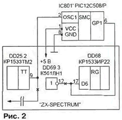
In Fig. 2 shows how to connect the PIC microcontroller with the ports of the I/o designed for cassette recorder, available in any SPECTRUM-compatible computer. Although in the video such microcontrollers nourish, generally, a voltage of 3.5 V. they work successfully and when the voltage of 5 In, so that no additional power source is not necessary point Shown the connection to the computer described in [3]. In other cases, you need find the digital input circuits connected through coupling capacitor with contact socket for connecting a tape recorder and a similar output.
The analysis program is written in basic and are shown in table. 1. It forms clock pulses in the discharge D3 port 0FEH and checks the state of discharge in D6 same port (this is the standard ZX-SPECTRUM address and the discharge port of the tape). To accelerate the operation of time-critical execution of the subroutine is written in assembler Z80 microprocessor. Their codes recorded in the DATA and operators loaded into the RAM of the computer, starting with 30000 cells (row 30). Appeal to assembler subroutines - using operators in RANDOMIZE USR lines 110 and 120.
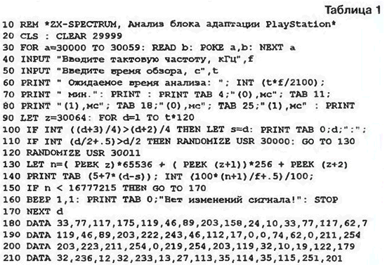
After starting the program you must enter a value of clock frequency in kilohertz and the duration of the sample interval of operation of the microcontroller (usually 10... 15 C). The analysis procedure is an 18...25 min. the frequency of the generated clock pulses of about 40 kHz, and if the ZX-SPECTRUM turbo - about 60 kHz. When the transition of the signal for analysis to a different level changing border color of the screen. The low level corresponds to black color, high white. At the same time the program displays the measured length of the time interval, in during which the signal level remained unchanged.
The data on the screen are arranged in four columns, with odd numbers in the columns correspond to intervals of low and even high level. For the convenience of analysis, they are rounded to the nearest hundredth of a millisecond (line 140). If all operators replace PRINT to LPRINT, the results will print to the printer. When the absence of changes of the analyzed signal for about 8 min program beeps, displays a warning message and stops (line 160).
In table. 2 shows the results of measuring the duration of the first 100 intervals signal Q2 of the block adaptation of a video game console SCPH-5502 at a clock frequency of 4,433 MHz. The first should be a short low level pulse, associated, obviously, with initialization of the microcontroller. The next long pulse high level coincides with the initial signal settings "PlayStation" after turning on power.
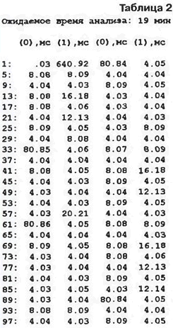
In some of the audited units of adaptation of this pulse or no level low. Further cyclically repeated three code sequence pulse (KP). separated by pauses, intervals low logic level duration of about 80 MS. It is easy to notice that all intervals approximately a multiple of 4 MS, which confirms the results of measurements made with using the oscilloscope. Taking as a unit and T denoting the value of 4 MS. get a timing diagram of the signal Q2, shown in Fig. 3.

The first 36 cycles of all three KP are identical, differ only bars 37-41, and in measure 42, preceding the pause between KP, there is always a logical 1. Working hypothesis - each KP is the "key" to a particular model "PlayStation", and studied the block generates three "key". Can theoretically be 32 KP, distinguished the logic levels in five cycles, from 37th to 41st. Further, speaking of KP. we we will try to set only the variable part of the code that are in these cycles.
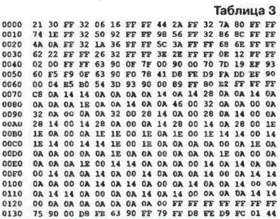
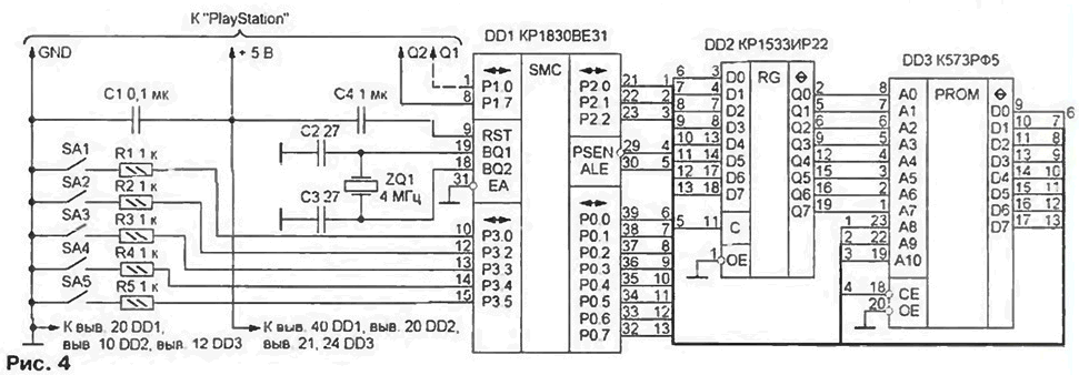
For further research will be required programmable pulse generator sequences. In Fig. 4 shows a diagram of such a generator for microcomputers CRUE (CRUE). The programme of work (tab. 3) recorded in the ROM DD3 CRF (CRF). Register-address latch DD2 is enabled by the standard scheme. Switches SA1-SA5 set the logic levels of the variable part of KP. For example, setting the switches SA1 and SA3 in a closed (0). and the rest are open (1) position, get KP with code 11010.
Feed device from the source of +5 In the "PlayStation". It consumes about 70 mA. If the generator set chip CRI (CRI). better to use an external power supply because the supply current will increase up to 150...200 mA.
The signal output from any of the four bits of port P1.4-P1.7 (pins 5-8 chip DD1) is served instead of the signal Q2 of the interface box on pin 17 of the chip SC4309xx or the output 42 of the chip CXD2938Q on the game console. For exceptions surprises all the rest, except for Q2, the findings of the adaptation block must remain in their seats.
First of all, set the switches SA1-SA5 one of the variants of KP. Set in the top box of any drive and press "RESET" to run it. If at least one "generic" disk needs at least one slot the program code is matched correctly. When the wrong choice of KP on the TV screen appears, warning about the impossibility of further work. Can to change the position of the switches SA1-SA5, not turning off the power. A survey of their the state produces about four times per second.
Experimentally established that for each model "PlayStation" there is only one KP (let's call it key), which "non-branded" discs are launched. For example, SCPH-1001 code - 10110. for SCPH-5502. SCPH-7502. SCPH-9002 - 01110. and for SCPH-5501 - 11110. It is not excluded, I can see other options.
Another useful observation is the key KP can follow not only to each other, but also be interleaved with other, for example, contains the "keys" for different models "PlayStation". Apparently, operating system, video game console looking at all accept KP. and the wrong "key" this work does not stop. The search continues 10 to 12-S.
It remains to determine to what extent it is possible to vary the timing parameters KP. This will have to change the byte value of the program generator to the address N as long as the game does not stop normally be imposed. Experiments have proved, that the allowed quantum duration T in the range 3.8...4.2 MS. Play with absolute precision time intervals in accordance with, for example, PL. 2 not definitely.
Then programmatically adjust the pause duration between KP, leaving unchanged the remaining intervals. It turns out that, without prejudice to enter the game programs it can last from 16 to 65T, and some video even up to 1000 TONS. Now I understand why some blocks generate adaptation KP with a pause not 20, and 22 or 23K.
Sometimes an adaptation block generates the signals, the parameters of which, at first glance, do not fit into the newly constructed theory. If we exclude the cases normal programmer errors, it should be recognized that the methods of protection key KP designed to create the greatest difficulty for those who try to figure out the law signal Q2. For example, one of the studied blocks generated the signal in which the first 14 KP differed from the key only. what's in them there was no tact 40, and the total length was 41, 42T and not. They were all false, and only every fifteenth KP is fully consistent with the key code 01110. And this is not an isolated case. Often key KP mask three to eight false.
In such "traps" come across those who do not bother to check all the options. In addition, it is very difficult to detect key KP using an oscilloscope, when the screen mask it with numerous nearly coincident with it false. Certain complexity and creates a violation of the strict periodicity of the signal. Often the interval T intentionally chaotic change. Attempts exact reproduction of this chaos (as it turned out, unnecessary) cause the greatest programmers difficulties. Nevertheless very rare, but there are not protected blocks adaptation. The signal is strictly periodic, and all generated KP - key.
Knowing the law of formation of key KP, you can make a homemade adaptation block on the basis of any of the known microcontrollers, including PIC sh, sh PIC from Microchip Technology, Z86xxx firm Zilog. Athh Atmel, SX18xx company Scenix. They Micropower, relatively cheap, small, have built-in ROM. The main thing that there were in the chip itself, the programmer, references and program-debugger. Unfortunately, to collect all these components together can't.
We can solve the problem and using common microcomputer series CR. KM. having low power consumption and software compatible with the famous family MSC-51 Intel. Used for experiments pulse generator sequences - in fact, the ready adaptation block on microcomputers CRUE. In addition to the signal Q2, and it forms Q1 (in the program given in table. 3, it is provided). Recent shoot with any of the four Junior bits of port P1 (pins 1 - 4 DD1 chip), as shown in Fig. 4 a dashed line. Knowing key KP. switches SA1 - SA5 can replace the jumpers.
(click to enlarge)
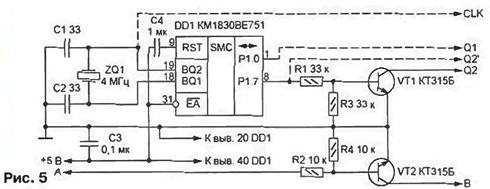
Greatly simplifies block the use of microcomputers with on-chip ROM with UV Erasure (CMI or KM1830BE7S3). In Fig. 5 shows the scheme of such device. The signal names and the connection point to different models "PlayStation" are identical to those specified in Fig. 1.
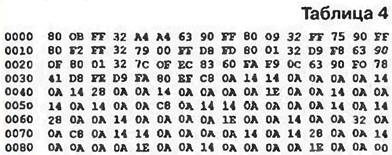
In the program memory of the chip DD1 write down the codes from the table. 4.
The timing diagram shown in Fig. 3, reproduced at the output Q2 of the key on the transistor VT2 simulates the channel A-b (see Fig. 1, d). A similar key on the transistor VT1 protects against high voltage the chip of processor Board video game console, which comes the signal Q2. Usually this chip is powered by a voltage of 3.5 V, and for the level of logic 1 (+5V) at the output of the microcomputer DD1 can be dangerous. If this is not so (for example, to the inputs of circuits SC4309xx permitted to submit as 3.5, and 5 V), the signals Q1 and Q2' are removed directly from the findings of the port P1 chip DD1, as shown in Fig. 5 dashed lines. Only need in the cell 000FH program memory chip DD1 replace the code 0FFH on N. what inverts formed signal.
Diagram of another version of a homemade adaptation block depicted in Fig. 6.
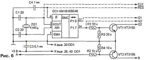
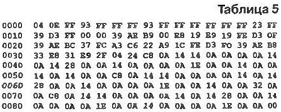
It different from the previous use of cheaper microcomputers CMO. His program - in table. 5.
Everything said above about the unit on the chip KM1830BE751, including replacing the code in the cell 000FH, is true in this case. The capacitor C4 can not install if file for output 4 signal DD1 from RES the top box. The disadvantage of such a substitution is the increased power consumption. To happiness, in fact, the current consumption is significantly less than the limit the values given in the reference books. Chip actually KMO consumes about 60 mA. Therefore, the device can be powered from the internal source "PlayStation" without fear of overload.
The frequency of a quartz resonator ZQ1 in each of the above blocks can be changed in wide limits. Thus it is necessary to choose a constant value, which is in cell N (PL. 3) or N (PL. 4 and 5) so that the quantum duration T was 4 msec. For example, if the frequency of the resonator 4,433 MHz. code N address N in table. 3 should be replaced at 48N. The same constant in table. 4 is located at the address N. In table. 5 address constants the same as in table. 4. but its value more. Here is the OPA should write N.
The law of alternation of time intervals in a KP formed set of numbers located in table. 4 and 5 the same way: option code 10110 is cells N-N. ID 11110 - in N-N, code 01110 - in N-EN. If the interval during which the output level is not changing, has a duration T, and is asked a number AN (decimal 10). intervals another duration is proportionally increased numbers. For example. SN (200 decimal) corresponds to the interval in 20T. If necessary, formed codes can be changed, but the cycle must end with a UN number, how to cell 008FH table. 4 and 5.
PCB blocks of adaptation, collected by the schemes of Fig. 5 and 6 is shown respectively in Fig. 7 and 8.
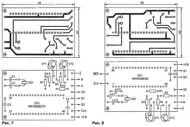
Boards are designed for the use of resistors ALT-0.125, capacitors, km-5, km-6. K10-17, the quartz resonator RC-169. Space to accommodate the adaptation block inside the "PlayStation" quite a bit. So in the manufacture should pay special attention to the thickness reduction of the device. The length of wires connecting it to the processor card, does not matter and can reach 300...400 mm. From the blocking capacitor C3 and resistors R3, R4 can be waived if it does not lead to malfunction of the unit. Instead the quartz resonator is allowed to use piezoceramic, for example, HCJ-4.00 MKC firm Herbert C. Jauch (Germany) with two internal capacitors with a capacity of 33 pF.
The resonator ZQ1 and capacitors C1, C2 can be omitted altogether, if take advantage of any available in the "PlayStation" clock signal TTL level a frequency of 3...5 MHz. It is fed through an isolation resistor 200...510 Ohms pin 19 of the chip CMO or pin 3 of chip CMI. Last does not coincide with the recommendations of [4], according to which on pins 2 and 3 should be feeding anti-phase clock signals. In practice, however chip operates even when reduced to 3.5 V voltage single-phase clock signal.
Another point that deserves attention. Some consoles "PlayStation" the first issues, for example, "American" SCPH-1001. only work with discs system NTSC. No selection code generated by the adaptation block, not to get this console to work with PAL discs. Obviously, in the case hardware adapted to process video signals of this system.
Literature
Author: S. Ryumik, Chernigov, Ukraine


