Low active hams on the band 136 kHz is due to the lack of appropriate equipment and antennas. It is the antenna on this band determine the effectiveness of the radio, as there is only really use much shorter emitters with very low efficiency.
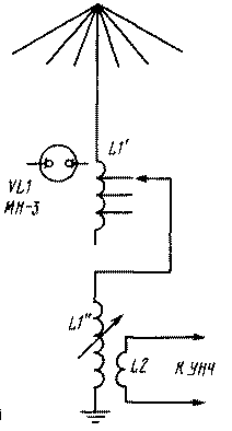
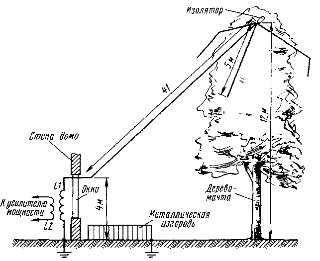
As a pilot transmission band antenna 136 kHz was tested with a wire antenna with a length of 41 m capacitive load at the end of the extension coil at the base (Fig. 1). The upper end of the antenna was attached to the tree at a height of about 12m above the ground (Fig. 2). Capacitive load five radiating conductors length of 5 m. They are made of coaxial cable with a diameter of 12 mm, the trailing ends of the cable must be insulated with resin.

Fig.1
A counterweight in these experiments served as a metal fence around the vegetable garden.
The wire that goes to the vertical part of the antenna and passing through the window frame, - coaxial cable with a diameter of 12 mm with the removed outer braid.

Fig.2
The capacity of the antenna, measured with respect to hedges of counterbalance, was 260 PF, i.e. to tune the antenna to resonance requires lengthening the coil with an inductance of about 5,26 mH.
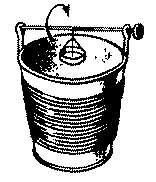
It was made up of two parts - coils L1' and L1". Coil L1' wound on a three-liter glass jar and contains 120 turns of wire sew-2 to 1.0. The length of the winding - 16 see Taps are made every 10 turns. The coil - 1,4 mH. For fixing it to the Bank was used parquet varnish. The coil L1 is wound on a plastic bucket with a diameter of 25 cm length 29 cm placed 180 turns of wire sew-2 to 1.0. The inductance of this coil is 4.8 mH. She adjusts short turns from a strip of copper foil with a width of 5 cm, suspended on nylon yarn (Fig. 3).

Fig.3
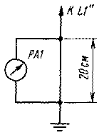
For matching the antenna impedance is used, the coil L2, placed in the lower part of the coil L1'. The choice of parameters L2 critical enough. The maximum antenna current was obtained when the number of turns of the coil L2 connection, is $ 40. To measure the antenna current was used improvised small-sized RF voltmeter connected in parallel to the conductor that goes from the coil L1 to ground (Fig. 4). He was enabled by the length of the wire 20 cm Active resistance of the two coils connected in series, measured at a constant current, was equal to 4.5 Ohms.

Fig.4
Configuring the transmitting antenna into resonance becomes quite critical. If the antenna resonance lies below the 136 kHz, reducing the inductance of the coil L1', adjust the antenna is in resonance with the smooth variations of the inductance L1". If the resonance lies above it, on the contrary, increase the inductance L1'. The change in the inductance L1' disconnect the transmitter and certainly the end from the L1" must be soldered to L1'. For indicating the antenna is useful to use a neon lamp VL1, attaching it with tape around the middle turns of the inner side of the banks, on which is wound a coil L1'. The transmitter in these experiments served as a low-frequency oscillator that is enabled through USC giving at a frequency of 136 kHz power 15 watts at 4 Ohms.
For admission in the range of 136 kHz used rebuilt radio "Ishim-003" is installed in the path of the inverter EMFs with a bandwidth of 500 Hz. It turned out that use a transmission antenna to the reception is impossible, since the input of the receiver input impedance 75 Ohms and the antenna was upset. I had to apply to receive some custom magnetic loop antenna. It is made on a wooden crosspiece size 140x140 cm and contains 140 m closed at the ends of the coaxial cable with a diameter of 6 mm.
In the resonance antenna is configured using constructed the variable capacitor from the old tube receiver. The coil - 10 m of the same cable. Bay held together with duct tape.
The antenna was mounted on the window that allowed you to select the direction of acceptance from Southeast to West. She clearly tuned into resonance, and as it rotates clearly felt the orientation in the admission of lightning discharges and pulsed signals of unknown origin.
As the nearby hams had no equipment and antennas in the range of 136 kHz, attempted to make their own signals. Receiver "Ishim-003" was exported to the country where the signals were confidently taken at a distance of 20 km In the next control point, at the distance of 35 km from the transmitting antenna, have found only a very weak signal.
Since the antenna has a good quality and at the ends of the conductors of the antenna and balances there is a high RF voltage, the antenna design and system balances should completely eliminate the possibility of accidental contact with her.
Author: Igor Grigorov (RK3ZK); Publication: N. Bolshakov, rf.atnn.ru


