Motorists are manufactured electronic components of the ignition, as a rule, the classical scheme, consisting of a high voltage source, cumulative capacitor and thyristor key. However, such devices have a number of significant disadvantages. The first is the low efficiency. Because the charge storage capacity can be likened to the charge of the capacitor through the resistor, the efficiency the charging circuit does not exceed 50%. So, about half consumed the power Converter will be allocated in the form of heat in the transistors. So they need extra heat sinks.
The second drawback is that during discharge of the capacitor thyristor short-circuits the output of the Converter and the oscillations produced by them are broken.
After discharging the storage capacitance thyristor is closed and the capacitor again starts charging smoothly increasing from zero to a maximum value, the voltage Converter. At high engine speeds this voltage may not reach the nominal value and the capacitor is not fully charged. It leads to the fact that with increasing number of revolutions decreases the energy of the spark.
A further disadvantage is due to the lack of stability of energy sparking when you change the voltage. When starting the engine with by means of a starter battery voltage can significantly (up to 9-8 In) to decline. In this case, the ignition unit gives out a weak spark or not working really.
Offer description electronic ignition, in which there is no these drawbacks. The device is based on the principle of the charge storage capacitor from stable in amplitude inverse ejection standby blocking oscillator. Value this release is only slightly dependent on the voltage of the vehicle electrical system and the number revolutions of the crankshaft of the engine, and therefore, the spark energy is almost always constant.
The device provides a level of potential on the storage capacitor in within 300 ± 30 V when you change the voltage on the battery 7 to 15 In, keeping in the temperature range -15 - +90°. Limit switching frequency is 300 pulses/s. supply current at f = 200 imp/s not more than 2 A.
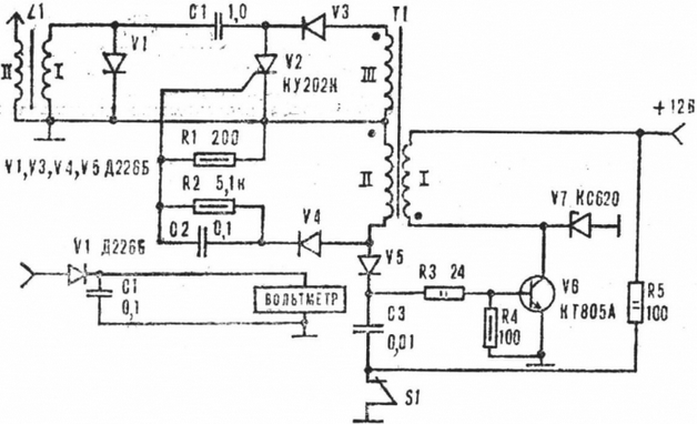
Schematic diagram of the electronic ignition (Fig. 1) consists of waiting the blocking oscillator transistor V6, transformer T1, the circuit formation trigger pulses C3R5, the storage capacitor C1, the pulse generator ignition of the thyristor V2.

Fig. 1. Schematic diagram of the electronic ignition
In the initial state, when the contact plate switch S1 is closed, transistor V6 is closed and the capacitor C3 is discharged. When contact opens it will charge through the chain of R5, R3, switch the base - emitter V6. The pulse charging current triggers the blocking oscillator. The rising edge of the pulse from winding II transformer (lower circuit output) triggers the thyristor V2, but since the capacitor C1 has not previously been charged, the device will not spark .
Once under the influence of the collector current V6 happen saturation the transformer core, the blocking oscillator will return to standby. The resulting discharge voltage at the collector V6, transforming into the winding III, through the diode V3 will charge the capacitor C1.
When re-opening of the breaker in the device, the same processes occur with the only difference that opened the front edge pulse thyristor V2 connect the now charged capacitor to the primary winding of the coil the ignition. The discharge current of C1 induces in the secondary winding of the high voltage bobbin the momentum.
Diode V1 suppresses spurious oscillations in the circuit formed by the capacitor C1 and the inductance of the primary winding of the ignition coil. Elements C2, R2, in the circuit the control electrode of the thyristor differentiate (shortened] pulses the blocking oscillator and diode V4 protects the electrode from the control strain with the duration of the release. In addition, V4 disables charged for the duration of the leading edge of the capacitor C2 to the base of the transistor. In the absence of the diode the blocking oscillator may move from inhibited the self-oscillating mode and disturbed the work of the entire device. The diode V5 performs a similar function, protecting the base of the junction transistor. The Zener diode V7 protects V6 from breakdown, if the unit is switched on without the reel or without spark plugs.
The device is insensitive to the contact plates rattling breaker. When they first opening the transistor V6 is opened and will remain in this state until the beginning of the saturation of the transformer regardless of the position of the breaker.
Transformer T1 is made on the yoke SLH with a gap of about 50 MK. Winding I contains 60 turns of wire sew-2 1,2, II-60 turns sew-2 0,31, III - 360 turns sew-2 0,31. The transformer core can be typed and from the W-shaped iron. However, due to rough trimming plate gap, even without the strip, can to be great. In this case, the necessary grinding irregularities at the junction of the magnetic circuit.
Transistor CTA can be replaced by CTB, but for higher values saturation voltage it will dissipate and some great power that can lead to self-start the blocking oscillator at high temperatures. Therefore, the transistor CTB it is advisable to install additional heat sink area of 20 - 30 cm2.
Instead of diodes DB you can apply KD105B - CDG, KDC - CDN (V1, V3), D (V4).
C1 is composed of two parallel connected capacitors MBGO-1 0.5 UF voltage of 500 V. C2 and C3 - MBM.
The thyristor CON permissible to replace CWM or CUI, COL. Because KU forward voltage does not exceed 300 volts, so the voltage on the cumulative the capacitor is reduced to 210 - 230 V by increasing its capacity up to 2 µf. Moreover, a noticeable effect on the energy of the spark is not provided.
To establish the device need avometr and simulator breaker - any electromagnetic relay, driven by a sound generator. The relay can be connected through step-down transformer to the lighting network. The frequency of the triggering pulses will then be equal to 100 pulses/s series-connected diode triggering frequency is 50 PPS.
If the items are in good working order and the terminals of the transformer are connected correctly, the device starts to work immediately. Verify that the voltage on the capacitor C1 was 300±30 V when you change the power value in the above range. Measure the voltage should peak voltmeter, taking advantage of the scheme, presented in figure 2.

Fig. 2. Circuit to measure the voltage on the storage capacitor
The device is connected to the junction point of elements C1, V2, V3 and by changing the size gap in the transformer core, to achieve the required voltage. If it is low, the thickness of the strip is increased. When reducing the gap the voltage must fall.
When the ambient temperature is low, the spark energy may fall. In this case it is necessary to reduce the value of the resistor RЗ because at low supply voltage the thyristor V2 may not open.
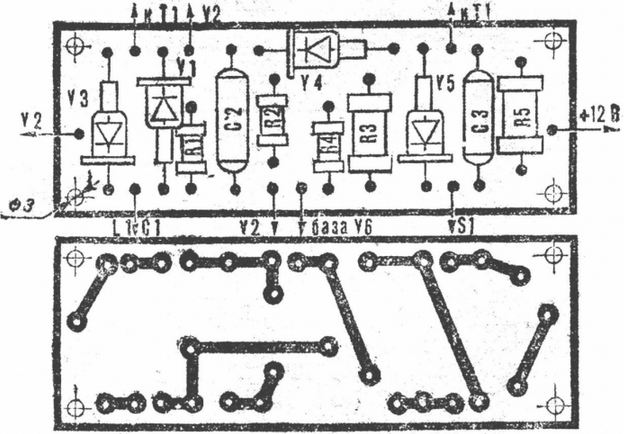
The mounting device is formed by a printing method on the Board size 95X35 mm, made of foil Micarta or fiberglass (Fig. 3).

Fig. 3. Circuit Board with the circuit arrangement of parts (M1:1)
Design implementation unit electronic ignition various - based on available material and the installation of the device.
Author: V. Bakouchev


