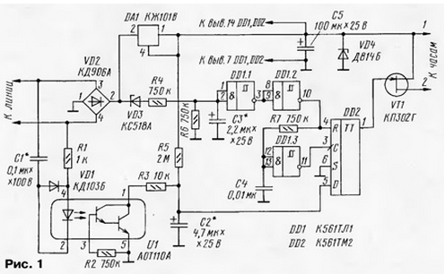
The prefix to the clock (Fig. 1) responds to outgoing calls. It contains rectifier diode bridge VD2, the voltage regulator on the chip DA1, the Zener diode VD4 and the capacitor C5, the comparator logic elements DD1.1- DD1.3, D-flip-flop on the chip DD2, electronic switches optocouplers U1 and transistor VT1.

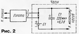
Connect the console to Electromechanical clock in accordance with the scheme shown in Fig. 2. This watch adds in the oxide capacitor C1.

Works console. After connecting it to the watch and a phone line in a few seconds, the capacitors C2 and C3 are charged: C2 through the resistor R5 to logic high, and C3 through the Zener diode VD3 and resistor R4. On the exit of the element DD1.2 is a high logic level, and the output of the trigger - low. The transistor is closed, the clock is de-energized.
If you pick up the phone, the line voltage decreases, the Zener diode VD3 closed. The voltage on the capacitor C3 in just a few seconds reduced to low level, and C2 will not change. At the exit of the element DD1.2 appears low logic level, and after a fraction of a second high level installed at the exit of the element DD1.3. This will lead to the same level the trigger output and, hence, to the opening of the transistor. The clock starts counting time.
If a tube put on the device, the line voltage will increase. After a few seconds, the capacitor C3 is charged, at the exit of the element DD1.2 will be high level. The trigger is reset, the transistor is closed, the clock will stop.
When you receive ringing signals through the emitting diode of the optocoupler will leak alternating current, will begin to open the phototransistor, and the capacitor C2 is quickly discharged. During the intervals between ringing signals it not be charged time. So if you pick up the phone, after a few seconds the output element DD1.3 appears a high level, and the trigger output is low. Transistor remain closed, watch the countdown begins.
Also indicated in the diagram, in the console is permissible to use the optocoupler ATB-OTG, OTA - OTG, OTA-ATV; transistor - or CPA KB; diode VD1 - any low-power rectifier; diode bridge VD2 - CDG, KDA either composed of four diodes KDA, KD102B or similar; the Zener diode VD3 - XA, VD4 - XA, XA, XI. Capacitor C1 is a series K73, C2, C3, C5 - K52, K53 or similar with a small current leakage, C4 - km. Resistors - MLT, S2-33.
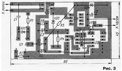
Parts mounted on the circuit Board (Fig. 3) of one-sided foil fiberglass. Board is placed in the housing of insulating material.

Establishing device is reduced to the selection of capacitors C2 and C3. Capacity capacitor C2 must be such that after a series of ringing signals tube removal clock does not turn on. It is possible to obtain this result will have to install a capacitor C1 with a larger capacity. The capacitor C3 is necessary to choose the capacity in which through 1...2 after removal of the tube on clockwork will receive the supply voltage.
I should add that the device needs to be used such Electromechanical or quartz watch with a mechanical dial that start counting time immediately after the supply voltage is connected.
Author: I. Nechaev


