


")

The main power switch, the circuit of which is shown in the figure, contains a small number of parts and consumes energy only during the moments of switching on and off. It is made on the basis of two-position polarized relay (remote switch) and is controlled by a push down button SB1.
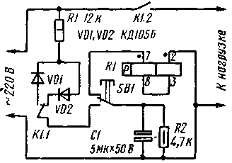
When you press the button, the capacitor C1 is quickly charged through the resistor R1 and the diode VD2 positive (relative to lower - scheme - wire network) voltage, and after releasing it - connected in series is discharged through the winding of relay K1. As a result, it is activated and its contacts building 1.2 connect the load to the network. and K1.1 prepare the unit for shutdown. The resistors of the divider R1, R2 are chosen so that the amplitude of the rectified diode VD2 voltage on the capacitor C1 does not exceed 40 V.
For disconnecting the load from the mains tap on the same button SB1. In this case, the capacitor C1 charges through resistor R1 and diode VD1 (now a negative voltage), and releasing it discharges through relay coil, switching it to its original state.
The device used a polarized relay RPS-20 (passport RS4.521.757). Non-polar capacitor C1 composed of two connected in series non-polar capacitor K50-6 capacitance of 10 μf (rated voltage 25 V). In the absence of such capacitors can be used two counter enabled polar (10 MCFH IN).
Establish the switch is not required. It should, however, be aware that when you disconnect a dial-up device using the power cord relay K1 remains in the same condition in which it was before this (automatic reset condition does not occur).
Author: I. Bushuev; Publication: N. Bolshakov, rf.atnn.ru