In devices of motor control rotation of the trays of the incubator [1, 2] apply the single-phase motor without reverse. These devices are applicable in small incubators, designed to the tab 30 to 50 eggs.
The article describes the control device of a three-phase motor any power connected to single-phase network. It can be applied in incubator farms with laying eggs from 500 PCs. (from the incubator of the refrigerator) up to 50 thousand units (industrial incubators such as "Universal"). It the device employs an incubator made out of the fridge, for 11 years.
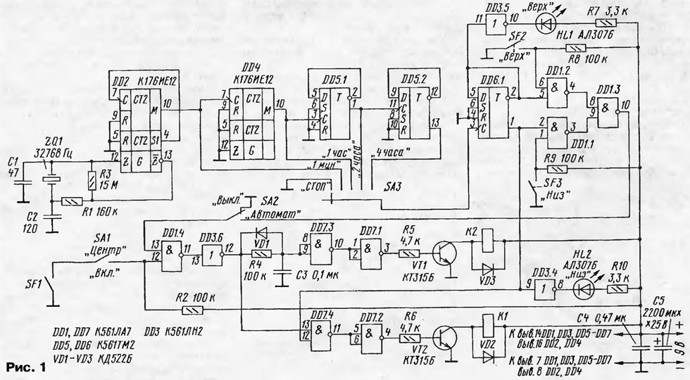
The design comprises a control and power blocks. The control unit (Fig. 1) includes generator and frequency dividers on the chip DD2, DD4, DD5, driver turning the engine on elements DD6.1, DD1.1-DD1.4, DD3.6, integrated circuit R4C3, keys on transistors VT1, VT2, relays K1, K2.

(click to enlarge)
The oscillator and the frequency divider up to the minute pulse is assembled according to the standard scheme on the chip DD2 (CIE). To divide up to 1 hour is used, the frequency divider 60 (IC DD4). Triggers DD5.1 and DD5.2 carry out the division to 2 and 4 hours. Switch SA3 select the time that will be to turn the trays. The duration of the output pulse of the trigger DD6.1 corresponds to the selected time period. The fronts of these pulses through the elements DD1.1-DD1.3 include the engine rotate trays.
On the front of the pulse with the direct output of the trigger DD6.1, passing through the elements DD7.4, DD7.2, moreover, includes reverse motor. The elements DD1.4, DD3.6 necessary to switch the operating modes "Manual" "Automatic" and install trays in a horizontal position the "Center".
To delay the restart of the engine after the reverse of the integrated circuit is R4C3. When specified on the diagram the values of this time is about 10 MS. Pulses management through the transistor switches VT1, VT2 include start relay K2 and engine the reverse relay K1.
When power is switched on one of the trigger outputs DD6.1 set high potential, for example, is output 1. If the limit switch SF3 is not closed, at the exit of the element DD1.3 is high level trigger relay K1, K2. The next time you switch trigger DD6.1 the reverse relay K1 is not activated, so as the input element DD7.4 will be served low. Relays K1 and K2 are included briefly, only at the time of rotation of the trays, as when triggered limit switches SF2 or SF3 at the exit of the element DD1.3 set low level.
Status display trays (top, bottom) is carried out by the LEDs HL1, HL2. The labels "Top" and "Bottom" indicate the position of the front edge of the tray and are conditional, since the direction of rotation of the motor is easy to change appropriate connection of the windings of the motor.
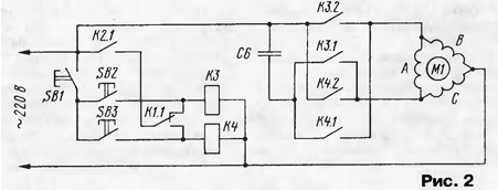
A diagram of the power unit shown in Fig. 2.

Relays K3 and K4 (alternately included) carry out switching of the motor windings and, therefore, control the direction of rotation of the rotor. Since relay K1 (if necessary) triggered before relay K2, and the inclusion of the motor contacts of K2.1 happens after you select the contacts K1.1 the relevant provision.
Button SB 1-SB3 duplicate contacts K2.1, K1.1 and are intended for manual set the position of the trays. Button SB1 constructively placed between buttons SB2 and SB3 for the convenience of simultaneous pressing of two buttons. Preferably under the top button to make the label "Top". The movement of the trays in manual mode should be performed in the position of the switch SA2 "Off".
The capacity of the phase-shifting capacitor C6 depends on the schema of the engine start (star, triangle) and its power [3]. For the engine included in the scheme "star", C=2800l/U, for inclusion under the scheme "triangle" C=4800l/U, where I=P/(1,73-Uη-cosφ); R - nameplate motor power in watts; cosφ - power factor; η - Efficiency; U is the voltage in volts; C - the capacitance of the capacitor in microfarad.
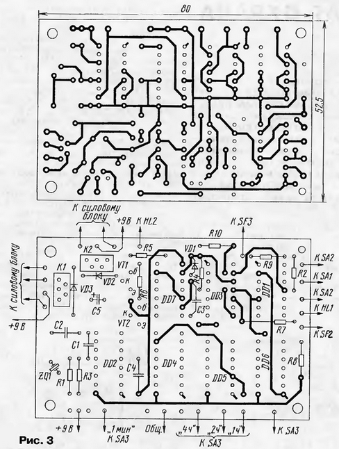
The device is assembled on a printed circuit Board (Fig. 3). Relay KZ, K4 and capacitor C6 located in the immediate vicinity of the engine.

The device incorporates the switches SA1, SA2 - P2K, SA3 - PG-9-PN. End switches SF1 - SF3 - MP. Relays K1 and K2 - RES, passport RF4.569.426. Relay KZ and K4 can be applied on any type of AC voltage of 220 V with the corresponding maximum current through the contacts. Three-phase motor M1 with the reducer can be used any with enough power on the shaft to rotate trays. You will need to take the weight of one egg approximately equal to 60 g, duck and Turkey meat 80 g, goose - 190 g [4]. Author version applied the engine FTT-0,08/4 power of 80 watts.
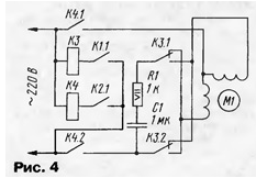
In Fig. 4 shows a device for controlling a single-phase motor.

Limit switches are arranged around the axis of rotation of trays required under angle. On the axis of the fixed sleeve with M8 thread into which is screwed the bolt, and bottom limit switches. Read more the design of the incubator from the case household refrigerator and recommendations for the incubation of eggs can be viewed at the web page <http:www.radic.newmail.ru>.
Literature
Author: N. Zaets, p. Valenica Belgorod region.


