


")

The scheme is intended for automatic maintenance the desired temperature with high accuracy and can find application in various industrial and domestic devices for controlling the heating chambers or soldering iron.
Main technical characteristics of heat stabilizer
1. Operating temperature range +150…1000 °C.
2. Precision maintain set temperature in the working range of not less than 2 °C.
3. Working voltage can be from 100 to 400 V.
4. Heater output is valid up to 4 kW (or 8 kW when using a heatsink for triac larger area).
5. The temperature sensor is the thermocouple from junction A Chromel - Alumel.
6. The control scheme has electric heat stabilizer isolation of DC from the power supply of the heater.
7. Switching circuit of the heater produced e non-contact way.
8. The power control circuit is powered from bipolar power supply with 12V voltage (current consumption of the control circuit does not exceed 15 mA). To one power supply permissible to connect up to 10 circuits thermal stabilizers.
The thermal stabilizer contains a minimal number of elements which ensures high reliability and small dimensions make it easy to place it in any case.
The device consists of two units: the control circuit and power unit.
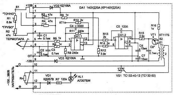
Fig. 1.17. Electrical diagram of a heat stabilizer
The control circuit (Fig. 1.17) is executed on a single dual chip DA1 (DA) and symmetrical thyristor (triac) VS1. On the element DA1.1 is assembled differential amplifier of the signal from the thermocouple, and DA1.2 - integrator, which controls the operation of the pulse generator on a unijunction transistor VT1. Pulses through the coupling transformer T1 is received in the switch VS1.
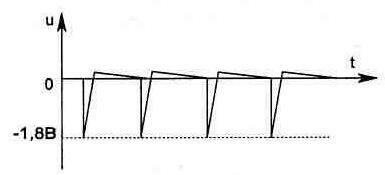
Fig. 1.18. The shape of the pulses on the control output of the triac
Using the circuit of the integrator is usually applicable comparator allows to provide a soft characteristic changes power to the heater when the output of the mode of thermal stabilization. This is done by changing the charge time of the capacitor C8, which determines the frequency generator, and hence the initial opening angle of the triac. Until the voltage from the output of DA1/12 will not exceed the threshold set by resistors R1 and R2 (DA1/6), the output circuits DA1/10 will +12 V voltage, which will provide the operation of the generator (VT1) at maximum frequency. In this case the shape of the pulses on the control electrode of the triac should be given in Fig. 1.18.
If the pulse shape is another, must be reversed conclusions to one of the windings of the transformer T1.
The electrical circuit of the power supply heat stabilizer can be assembled according to one shown in Fig. 1.19 variants. Both schemes have internal electronic overload protection and in particular the explanations are not needed, as they are typical. When using a single power source for multiple thermostabilizers the inclusion of each control circuit is separate the toggle switch.
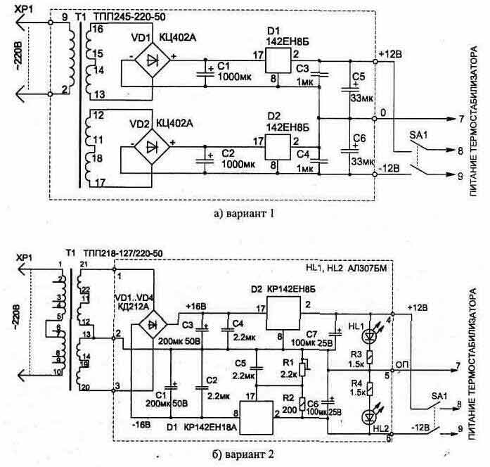
Fig. 1.19. Dvuhpolyarnyy power source for heat stabilizer
The PCB and the location details are given in Fig. 1.20 1.22.... The triac is mounted on the radiator, consisting of two copper plates, one of which is shown in Fig. 1.23. For ease of connection external circuit Board (Fig. 1.21) fixed screws MOH and M4 with nuts.
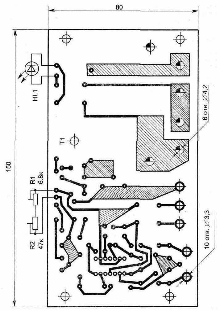
Fig. 1. 20. A printed circuit Board of the control circuit
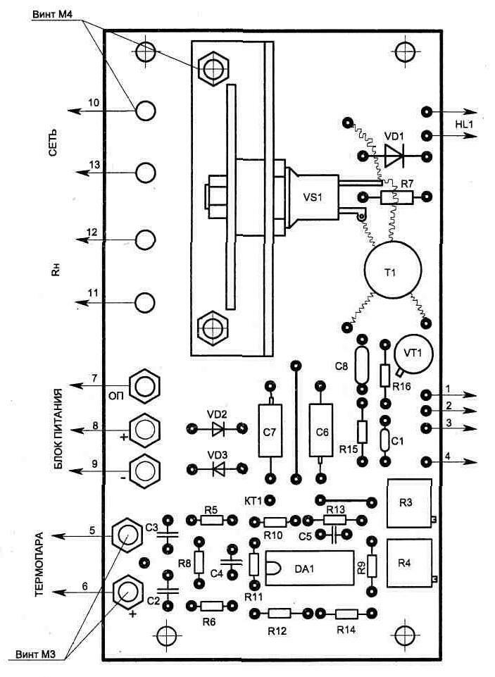
Rice, 1.21. The detailed location
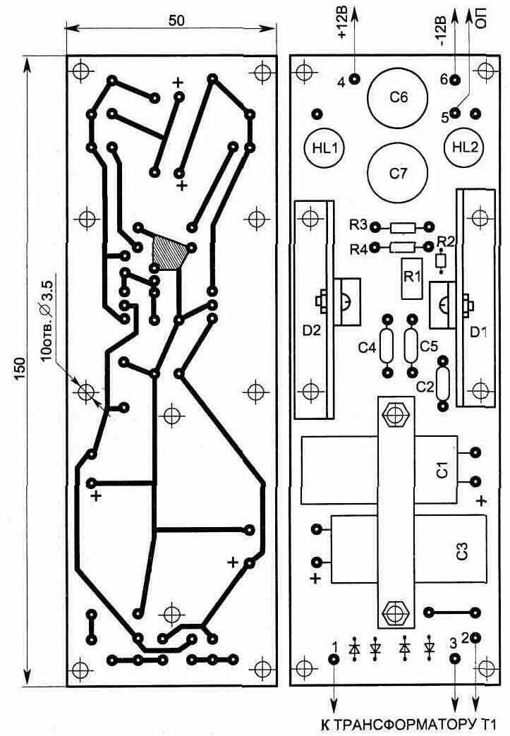
Fig. 1.22. Printed circuit Board power supply, option 2
The circuit has a precision integrated circuit, and replacement it to another type is invalid, as this will affect the accuracy of temperature maintenance due to the increase of zero drift, which will be commensurate with the magnitude of the signal from thermocouple.
Pulse transformer T1 is wound with wire PELSHO-0,18 on a ferrite ring MNM size CHH mm or ring MNM - CHH mm and contains in the winding 1 - 80 turns, 2-60 turns. Before winding the sharp edges of the core must be rounded with a file. Otherwise they will cut wire. After winding and impregnation of the coil with varnish must ensure the absence of leakage between windings and windings and ferrite frame.
Other parts of the circuit is not critical and may be of any type, for example: the variable resistors R1 and R2 type SDR-4A; R3 and R4 is rigged multi-SP5-2; fixed resistors C2-23; electrolytic capacitors C6 and C7 - K53-1A 16 In; other - type K10-17. Diodes VD2, VD3 are to protect the circuit against wrong connection of a power source and can be any, for currents up to 100 mA.
Connecting the control circuit, it is necessary to observe the phase position indicated in the figure (with the right connection on the radiator triac must be the phase of the mains voltage). This is especially important if from one power source includes several thermal stabilizers.
When power is supplied to the control circuit should be included heating load RH. The indicator of inclusion of a heater is the led glow HL1 or connected in parallel with the lamp load.
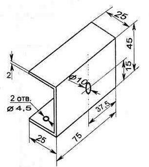
Fig. 1.23. Radiator design for triac
To set the temperature stabilization set in the middle position of the regulators R1, R2 and
waiting for the temperature rise in the heating zone to the desired value, the controller ROUGHLY get off of the heater.
When the process of thermal stabilization is established, correct the temperature controller can PRECISELY.
The scheme allows you to have some fixed values temperature when switch S1. In this case, the desired temperature can be adjusted relevant trimmer resistors R3 and R4 on the control Board.
Publication: www.cxem.net