


")

The device for displaying dynamic information are widely used in street advertising, as well as businesses, educational institutions, shopping malls and other institutions where there is a need to familiarize the audience with fleeting data and dynamic information flows. Amateur development this purpose has been repeatedly documented in periodicals. Their the main disadvantages, in addition to significant cost - dependence on data programmed into the chip ROM, the lack of operational capabilities change the displayed information, and in some cases, and the need the use of rare components. The proposed device is a console connected to the computer, made available on element base and has quite wide operational capabilities.
Compact dynamic setting (MDU) "omega" together with the software package tools can be used to organize the output of the display information as to character the form of a set of typical characters under the character generator, and graphic, which is set by the user from an arbitrary set of pixels. Works MDU running IBM-compatible personal computer (PC) with operating system MS DOS or Windows. The device has a compact size simple in operation, easily installed and requires no special knowledge to use. Unlike an industrial prototype, with minimal configuration (based PC with 80286 processor) has a low cost.
Block diagram of the device depicted in Fig. 1.
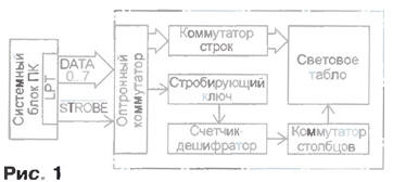
Controls its operation LPT the PC port. This uses the eight-bit data bus that specifies the number LEDs in the familiarity vertically or number of rows. Control of the data bus via the port address is 378h. Setting at this address signal code whose value can be between 0 and 255, can ask any combination of high and low levels on the data bus LPT port.
Signal code with LPT port is supplied to the opto switch rows that provides any combination of on and off LEDs vertically. For switching and vertical columns and create a dynamic horizontal scanner STROBE signal is used, which is generated programmatically when access port at the address 37Ah. Through the gate key signal is supplied to the counter-decoder synchronously with the change of signals on the data bus.
The counter-decoder controls the rotating operation of the key switch vertical columns of LEDs, creating a horizontal scan. Depending on and informative unit counter-decoder can be 8-, 16-, 32-, 64- or 128-bit, which provides a proportional change the number of vertical columns and respectively the length of the light-emitting screen. In the described device is used led displays, consisting of 32x8 elements (256 LEDs).
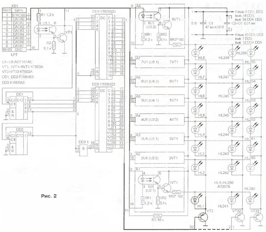
Schematic diagram of the device shown in Fig. 2.
(click to enlarge)
To ensure galvanic isolation and protect your PC from over-current that may be induced in the connecting wires at a great distance from MDU system unit and operation in harsh electromagnetic conditions, management the device is via an optocoupler keys U1.1 and 1U1-8U1 (U2.1-U5.2).
The data bus generated by the software at the output LPT port signal plug XS1 is input to the switch lines are implemented with optocouplers 1U1 8U1 and transistors 1VT1 8VT1. As a result come off appropriate the transistors included in the emitter circuit of the group of LEDs comprising vertical columns, through current limiting resistor 1R3-8R3 connect to the supply circuit of the device.
Changing the state of the data bus is accompanied by the appearance of the clock pulse on line Strobe LPT port. With the passage of this pulse through the optocoupler U1.1 activated the key on the VT1 transistor, which causes the state change counter DD1. Together with counter DD2 and the inverter DD3.It provides relevant 1 the operation of decoders DD4 and DD5 and alternately increasing their outputs connected with the switch of vertical columns, transistors VT2-VT33. In creates horizontal scan: the coincidence time of opening key switch rows and key switching and CSOs or vertical column the respective cathodes of the LEDs are connected to the power source device and lit. With the advent of the next clock pulse on the Strobe line and the change of signals on the data bus LEDs glow of the next column, and so D.
The device provides the output text of arbitrary length text file, as well as user-created graphic images from a data file.
To analyze the operation of the software device, having considered below are fragments of programs written in TurboBASIC. Program designed to connect the MDU to the LPT1 port address 378h, while managing horizontal scan occurs on Strobe line when referring to port 37Ah.
'Alternately, the inclusion of elements
'tov one vertical column
out &h378,1: delay .3
out &h378,2: delay .3
out &h378,4: delay .3
out &h378,8: delay .3
out&h378,16: delay .3
out &h378,32: delay .3
out &h378,64: delay .3
out &h378,128: delay .3
out &h378,0: delay .3
end
'Alternately, the inclusion of elements
'tov one vertical column
for i=1 to 10
for j-0 to 7
out &h378,2^j
delay .05
next j
next i
end
'Luminous fill
'elements of one column
for i=0 to 255
out &h378,i
deJay .028
next
end
'The effect of "Running a column"
for e=0 to 31
out &h378,255
out &h37A,0:
for q=0 to 3100: next q
out &h37A, 1:
for w=0 to 3100: next w
next e
end
'The effect of "Running diagonal for i=1 to 10 for j=0 to 7
out &h37A,0: out &h378,24
for k=0 to 80: next k
out &h37A,1: for 1=0 to 80: next 1
next j
next i
end
'The glow of all the elements
for e=0 to 3100
out &h378,255:
for r=0 to 10: next r
out &h37A,0:
for q=0 to 1: next q
out &h37A. 1:
for w=0 to 10: next w
next e
out &h378,0
end
Developed by the author device software
The device is mounted on the PCB size 250x110 mm from bilateral foil fiberglass (Fig. 3).
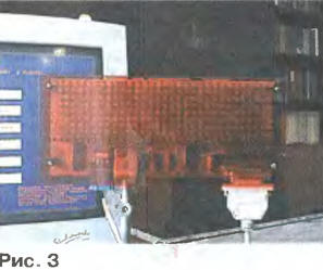
The drawing Board is available online at the same address, and software. The installation should be taken into account that certain parts should perform the functions of the jumpers connecting printed conductors on different sides of the Board, so they should be soldered to printed conductors on both sides. The blocking capacitors C2-C6 solder directly to the power pins of the ICS DD1, DD2 and DD4, DD5. After the installation of LEDs is closed by a plate of transparent organic glass of red.
To operate the device in a minimum configuration sufficient to have the system unit Based PC 80286 CPU with keyboard and floppy drive (monitor not required). Nourish MDU from an independent source with an output voltage of 5 V at currents up to 0.5 A to enhance the brightness of the LEDs can decrease the resistors 1R3-8R3 however, to choose less than 20 Ohm not recommended, as environments the value of the current through the led can exceed the maximum allowed.
The circuit approach allows to create device with a number of vertical columns from 8 to 128, and the number light-emitting elements can vary from 64 to 1024 Should however note that when the number of columns 64, the brightness is reduced To the brightness and size of display elements of a valid parallel the inclusion of the four LEDs in one light-emitting cell (every other your current limiting resistor). Thus it is desirable to use LEDs with the light emitting surface in rectangular shape.
Author: O. Geluk, Rivne, Ukraine