


")

A distinctive feature of this device is a count of the number of people in the room. This allows you to automatically turn on lights when the input of the first person and turn it off when you exit the last.
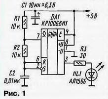
The machine consists of transmitting and receiving blocks. In the transmitting unit (Fig. 1) is a generator of rectangular pulses with a frequency of 3 kHz on-chip and 0A1 installed at the entrance to the room IR led HL1, which converts these pulses in the infrared flash.
Opposite the LEDs HL1 posted photodiodes VD1, VD2 of the receiving unit (Fig. 2), transforming light impulses into electrical. In the initial state of this block in the DD3 counter recorded the number 15 and the carry output R (vyv. 7) signal is a low logic level, prohibiting the inclusion of lighting. The pulses coming from the photodiodes VD1, VD2. amplified circuits DA1, DA2 and through resistors R4, R8 act on bases of the transistors VT1, VT2, periodically open and drain the capacitors C11, C12. As a result the inputs of the elements DD2.1 and DD1.3 receives a signal of low logical level. Like this same level will be present at the input (pin. 13) of the element DD2.4 that prohibits the change of the signal level at the input of the counting direction of the counter when you change DD3 the state of the RS-flip-flop on the elements DD1.1 and DD1.2. On the output RS-flip-flop on the elements DD2.2 and DD2.3 in this state, the receiving unit also there will be a low logic signal level.
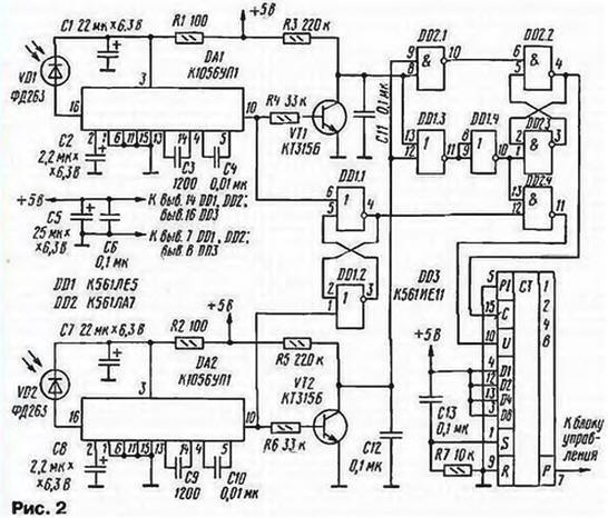
When a person enters the room, he first interrupts the infrared rays falling on photodiode VD1. The pulses present at the output circuits DA1 and periodically opening the transistor VT1, will disappear, will begin charging the capacitor C11 and to the respective inputs of the elements DD2.1 and DD1.3 the alarm log. 1.
Will disappear and the voltage sup plied to the inputs of the trigger DD1.1, DD1.2, the output also displays the level of the log. 1. At the output of the element DD2.4 encounter determining the direction of movement of the level of the log. 0. Continuing the movement, included in the room people will block and IR rays. falling on the photodiode VD2 that will lead to the disappearance of the pulses at the output of the chip of DA2 and charging capacitor C12. However, the trigger on the elements DD1.1, DD1.2 does not change its state, and the trigger on the elements DD2.2, DD2.3 switches in a single state, and the DD3 counter will count one pulse in the direction defined by the state of the trigger on the elements DD1.1, DD1.2.
Moving on, the person first get out of the way for the IR rays falling on the photodiode VD1, and then to the led VD2. Now at the outputs of circuits DA1, DA2 pulses appear, which will begin to open the transistors VT1, VT2, leading to discharge of the capacitors C11, C12. In the end, to the inputs of the element DD1.3 goes from the low logic level, the trigger on the elements DD2.2, DD2.3 changes status. The entire device going back to the original position, but the counter will be recorded the number, the number of people in the room, and if it is not is zero, the carry output of the counter will be present the signal log. 1. allowing the lights to come on. Chart of voltages in the receiving elements block is shown in Fig. 3.
When the person leaves the premises, the device works in a similar way for except that at the time of output of the trigger DD1.1, DD1.2 will be to present the level of the log. 0 and define them for the DD3 counter will be the opposite.
The maximum number counted by the counter people equals 15, then counter DD3 starts counting again.
Chain R7C13 sets the counter to the initial state after power-up.
To the output of the machine is connected to the actuating relay. Diagram of one possible variants shown in Fig. 4. When the input voltage high level the VT1 transistor opens, the electromagnetic relay K1 is activated and its the closed contacts include lighting.
As the expense occurs while overlapping access the IR beams to both the photodiodes, and in the initial state the device is returned after the IR rays simultaneously affect both the photodiode, excludes all error, associated with the uneven movements of the order of hit The infrared rays on the photodiodes.
As a power source you can use any stable unit power on +5 V with a load current of 0.2 A.
The device is mounted on three printed circuit boards of foil fiberglass thickness of 1.5 mm. At first posted details of the transmitting unit (see Fig. 1), the second - receiving (see Fig. 2). the third Executive relay (see Fig. 3) and a power source.
The first two boards should be installed on opposite sides of the door jamb so that the infrared rays led falling on the photodiodes and took place at the height of the man's chest.
The photodiodes should be placed on the same level at the distance of 60 mm from each other and so that part of the room the man first blocking the infrared rays, falling on the photodiode VD1.
In the machine may be possible to apply resistors MLT-0,125 and any small-sized capacitors. In place of transistors VT1, VT2 (see Fig. 2) and VT1 (Fig. 4) can to work KT315 with any alphabetic indices. Diode VD1 (Fig. 4)-any low-power silicon. Electromagnetic relays K1 - RAS (passport RS4.524.203) or any other operating steadily at a voltage of 5 V and having contacts on the voltage 220 and In striking the appropriate load current.
Establishing device start with checking the pulses on the led HL1 emitting unit (see Fig. 1). After that, check for pulses at the output circuits DA1, DA2 (pin 10) of the receiver (see Fig. 2). If the pulses missing or their shape is strongly distorted, change the position of the led and photodiodes and choose the capacitance of the capacitors C2, C8.
Author: S. Kuleshov, Kurgan